background image


10


It is recommended that only an authorized MagnuM installer install your wood pellet stove.

  The following installation 

guidelines must be followed to ensure conformity with both the safety listing of this stove and to local building codes. 

9


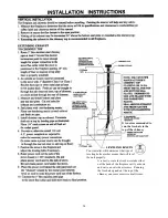
A listed 3” or 4” type “PL” pellet vent exhaust system must be used for FREESTANDING installation and attached to the 
pipe connector provided on the back of the stove.  Use a 3” to 4” adapter for 4” pipe.  A cap must be used at the 
termination of type “L” vent chimneys. 


9


Do not terminate vent in any 

enclosed or semi-enclosed

 area, such as; carports, garage, attic, crawl space, under a sundeck 

or porch, narrow walkway or closed area, or any location that can build up a concentration of fumes such as a stairwell, 
covered breezeway, etc. 


9


Vent surfaces can get hot enough to cause burns if touched by children.  Non-combustible  shielding or guards may be 
required.  

Do not install a flue damper in the exhaust vent of this unit. 


9


Termination must exhaust above air inlet elevation. 

 It is recommended

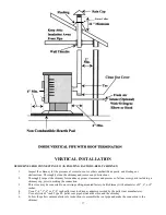
GUIDELINES FOR EXHAUST VENTING SYSTEMS DESIGN 

 that at least 3 ft. of vertical pipe be installed 

when the appliance is vented directly through a wall or in a basement.

  This will create some natural draft to prevent 

the possibility of smoke or odor during appliance shutdown and to keep exhaust from causing a nuisance or hazard from 
exposing people or shrubs to high temperatures.  In any case, the safest and preferred venting method is to extend the vent 
through the roof.  

Do not connect this unit to a chimney flue serving another appliance. 


9


Distance from doors and windows, gravity or ventilation air inlet into building: 

Not less that 4 ft. / 1.2 m below, 4 ft. / 1.2 m horizontally from, 1 ft. / 305 mm above (This does not apply if the 
windows are non-opening or have been fixed so they cannot open.) 

9


Distance from bottom of termination and grade – 1 ft. / 305 mm minimum.  This is conditional upon the plants and nature 
of grade surface.  The exhaust gases are not hot enough to ignite grass, plants or shrubs located in the vicinity of the 
termination.  The grade surface must not be a lawn.  Distance from bottom of termination and public walkway is 7ft. /2.1m 
minimum. 


9


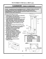
Distance to combustible materials – 2 ft. / 610 mm.  This includes adjacent building, fences, protruding parts of the 
structure, roof overhang, plants and shrubs, etc. 


9


It is recommended that a single or double clean-out “tee”, for cleaning the vent in both directions, be installed at every 90-
degree junction


to enable collection of fly ash and to permit periodic cleaning of the exhaust system.  90-degree elbows 

accumulate fly ash and soot, thereby reducing exhaust flow and performance of the stove. 


9


Total length of horizontal vent must not exceed 10 feet / 3,000 mm.  All joints in the vent system must be fastened by at 
least three (3) screws, and all joints must be sealed with 

high temp 

RTVsilicone sealer to be airtight. 


9


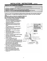
A 3” inch single-wall, stainless steel flexible or rigid exhaust pipe should be used for INSERT installations and must be 
attached to the stove with a single-wall, stainless steel “tee” with a clean-out cap.  The stainless steel “tee” should be 
inclined at 45-degrees to enable the vent to be centered on the stove and allow the “tee” to be cleaned without removing 
the stove (see diagram 11.1). 


9


When venting into an existing masonry or factory built chimney, the chimney must be cleaned, with all creosote removed.  
The chimney must be a type suited for solid fuel.  

WARNING:

 The chimney and the chimney connections must be kept 

clean and in good condition. 


9


The “PL” venting or single wall stainless exhaust system must be installed so as to be GAS TIGHT!  The vent 
manufacturer’s installation procedures must be followed.  In addition, pipe connections, joints and all pipe seams within 
the home should be sealed with high temperature RTV silicone sealer. 


9


If an insert is to be installed into an unlined masonry chimney, it is recommended that a 3” or 4” inch stainless steel pipe 
be extended to the top of the existing chimney.  The top of the existing chimney should be sealed with a steel plate (see 
diagram 11.2). 


Содержание Winchester WINACI

Страница 1: ...ve pressure All chimney connections elbows and fittings must be airtight Proper venting practices must be followed Consult with a venting professional 9 Ashes must be disposed of in a metal container with a tight fitting lid 9 All minimum clearances to combustibles must be followed 9 The MagnuM Corn Biomass Wood Pellet Stove is tested for operation with wood pellets with an ash content of no more ...

Страница 2: ...ures 36 Glass Maintenance Adjustment Removal and Replacement 37 Circuit Board Functions 38 39 Setting the Draft 40 Wiring Diagram AC DC 41 42 Draft Slide Gate Adjustment 43 Solar Panel Connections 43 Igniter Replacement 44 Trouble Shoot Guide 45 46 47 48 MagnuM Winchester Replacement Parts List 49 Warranty 50 Service Record 51 TESTING CERTIFICATION INFORMATION The MagnuM WIN stove report 150 S 01b...

Страница 3: ... American Energy Systems Inc manufacturer of the MagnuM Winchester Appliances reserves the right to alter its products their specifications and or price without notice Safety tested and EPA exemption tested by Omni to UL 1482 CAN ULC S627 ULC S628 APFI requirements Oregon administrative rules 814 23 900 to 814 23 909 and E P A Method 28A Winchester Insert Heating range 8 000 40 000 BTU SPECIFICATI...

Страница 4: ...stove or it could be that there is a serious lacking of good quality air in the home caused by negative pressure If you have done any remodeling or if this is a newer home it is a very real possibility that this is happening Most basements have negative pressure even if you feel that your home is drafty This is called the stack or chimney effect If there is a black coating of soot coming into the ...

Страница 5: ...ed If you are burning fuels not approved for this appliance it will void the warranty and no service warranty will be allowed 9 The MagnuM models will burn high ash content fuels but will require additional maintenance cleaning 9 A working smoke detector must be installed in the same room as this product 9 It is recommended that a fire extinguisher class a b c be installed close to the appliance 9...

Страница 6: ...ontent periodically to maintain the proper dryness 9 Check your corn for foreign objects Your stove warranty will not cover damage done to your stove due to foreign objects in the fuel supply 9 Do not carry your corn supply over into the next heating season if possible unless properly stored If you carry over your corn supply make sure to check the corn for proper moisture content 9 DO NOT BURN TR...

Страница 7: ...en cleanings Only wood pellets manufactured to the Association of Pellet Fuel Industries A P F I standard for residential pellet fuels are recommended Look for A P F I registration number on the back of pellets Consult your local MagnuM reseller for more information on approved wood pellet fuel 9 It is strongly recommended not to keep a supply of wood pellets over the summer months Moisture will b...

Страница 8: ...ile you are attaching the leg The casting could break if bound or dropped NOTE It is best to attach the legs on one side first and then lift the unit up level to attach the other side You can also attach the legs on the back two corners first and then the front Place the nut on the bolt that is located on the base of the unit and attach the leg to the bolt Swing the leg so that the foot of the leg...

Страница 9: ...tection must be 3 8 inch minimum thickness non combustible material or equivalent extending beneath heater and to the front side rear as indicated CHIMNEY AND CONNECTOR 3 LISTED PELLET VENT ONLY NOTE REGARDLESS OF STOVE CLEARANCE VENT PIPE MUST ALWAYS HAVE A 3 INCH CLEARANCE ALCOVE CLEARANCES MIN ALCOVE WIDTH 27 In 694 mm MIN ALCOVE HEIGHT 47 In 1194 mm MAX ALCOVE DEPTH 36 In 914 mm WARNING THE MI...

Страница 10: ...surface The exhaust gases are not hot enough to ignite grass plants or shrubs located in the vicinity of the termination The grade surface must not be a lawn Distance from bottom of termination and public walkway is 7ft 2 1m minimum 9 Distance to combustible materials 2 ft 610 mm This includes adjacent building fences protruding parts of the structure roof overhang plants and shrubs etc 9 It is re...

Страница 11: ...th should not exceed 30 feet Diagram 11 1 Component Equivalent Length Equivalent Pipe Length Horizontal Straight Pipe Actual Length in ft x 1 0 Horizontal Pipe 1 x 2 1 3 ft Vertical Straight Pipe Actual Length in ft x 0 5 Vertical Pipe 0 5 x 8 4 ft 900 Elbow or Tee 5 0 feet 90 Degree Tee 2 x 5 10 ft 450 Elbow 3 0 feet 45 Degree Tee 1 x 3 3 ft TOTAL 20 ft NOTE These are guidelines only Proper venti...

Страница 12: ...omer s responsibility to make sure that there is adequate fresh air to the home so that the MagnuM appliance does not become the fresh air source 4 Only non combustible piping 3 inches in diameter is approved to use for outside air connections straight or flexible PVC pipe is NOT approved and should NEVER be used 5 If the air inlet is connected to the outside it MUST be terminated with a vertical ...

Страница 13: ...r local building codes fire codes and the safety listing tag on the inside hopper lid An outside air source must be connected to the stove and can be brought in through the sidewall or vented crawl space Flexible or rigid pipe should be used and will connect to the adaptor on the back of the stove See air inlet location under the CLEARANCE section of this manual Place the stove where you will enjo...

Страница 14: ... THE FOLLOWING REQUIREMENTS ARE MANDATORY FOR INSTALLATION IN A MOBILE HOME 1 Stove must be permanently bolted to the floor 2 Stove must have permanent outside air source 3 Stove must be permanently electrically ground to the steel chassis of the mobile home 12 ga or larger wire 4 All vertical chimney vent must have wall supports every five 5 feet 5 All exhaust systems must have a spark arrestor W...

Страница 15: ... the pellet vent manufacturer s instructions Connect the pipe and lock the joints as directed by the pellet vent manufacturer and secure the vent pipe to the flue collar on the back of the stove Add a small bead of RTV high temperature silicone around the outside edge of the flue collar prior to securing the vent pipe Drill and attach the vent pipe to the flue collar with sheet metal screws Altern...

Страница 16: ...ote The pipe lengths shown are for reference only Your actual pipe length requirements may differ SINGLE WALL PIPE SHALL NOT BE USED FOR ANY INSTALLATION HORIZONTAL INSTALLATION SHALL BE A MAXIMUM OF 5 FEET WARNING Vent surfaces can become hot enough to cause burns if touched Non combustible shielding may be required PLEASE FOLLOW THE PELLET VENT MANUFACTURER S INSTRUCTIONS AND LOCAL BUILDING CODE...

Страница 17: ...s and presence of all necessary parts including a chimney cap prior to making the connection 3 This stove may be connected to an existing ceiling mounted factory built chimney with a diameter of 4 6 or 8 inches 4 Use a 3 4 3 6 or 3 8 inch pellet vent to chimney adapter provided by the pellet vent manufacturer 5 Use only listed 3 inch Type PL pellet vent pipe between the stove and the chimney 6 Fol...

Страница 18: ...ash buildup premature failure of exhaust system staining of the house siding and serious creosote buildup This installation should not be used in a cold climate area Storm Collar Note This type of installation is not recommended in cold climates unless closed in and insulated properly required 3 min 18 ...

Страница 19: ...two terminals on the back of the control panel When the room temperature drops below the thermostat setting the thermostat switch will close allowing the stove to operate at the medium or higher settings When the room temperature matches the thermostat setting the thermostat switch will open allowing the stove to operate at the low setting 8 Locate the control panel into the side panel cut out and...

Страница 20: ... to the two terminals on the back of the control panel When the room temperature drops below the thermostat setting the thermostat switch will close allowing the stove to operate at the medium or higher settings When the room temperature matches the thermostat setting the thermostat switch will open allowing the stove to operate at the low setting 17 Locate the control panel into the side panel cu...

Страница 21: ...21 MAGNUM WIN INSERT INSTALLATION ...

Страница 22: ...22 WIN INSERT INSTALLATION cont Siding Use only rigid Pellet Vent pipe Framing Chimney cap Storm Collar Seal Plate 3 75mm Minimum Clearance Around vent 6 150mm min 16 375mm minimum 6 150mm minimum ...

Страница 23: ...st use some type of supp bolt to hold and lev the unit not provided ort el For a raised Hearth you can have a decorative skirting made by your installer to finish off the front of the unit The skirting must be made out of non combustible materials and must support the weight of the unit ...

Страница 24: ...fresh air intake either out the back of the fireplace cavity or down and out to an outside air source Running the fresh air up and out the top of the chimney can cause excessive draft issues Your installer will determine what type of leveling bolts or other means that will level the unit properly ...

Страница 25: ...25 ...

Страница 26: ...Fireplace Insert Shroud Installation Diagram 26 ...

Страница 27: ...27 Thermostat wire connection Low voltage thermostat Molex Plug 24 volt thermostat hookup ...

Страница 28: ...p to prevent moisture from reaching terminals see diagram 8 Connect the red positive lead to the positive battery terminal 9 Connect the black negative lead to the negative battery terminal 10 Reconnect the 110 volt AC power The stove is now ready for 12 volt back up and will switch automatically to 12 volt operation when AC power is lost When AC power is restored the stove will automatically swit...

Страница 29: ...e is not started within the minimum cycle time the auger will stop feeding and you will need to start the cycle over again Pushing and holding the auger switch allows you to prime the auger and add fuel to the firepot automatically This can be done app 1 minute after pushing the on off start button The unit starts automatically on the low heat setting When you have started the unit app 10 minutes ...

Страница 30: ...on allows you to prime the auger and add fuel to the firepot automatically Press and hold the button until you have the right fuel load Do not continue to hold the auger button under normal operation as it could overload the firepot smother the fire and lead to a dangerous condition The convection blower speed varies directly with the feed rate The Fan le fan function when pressed It will set the ...

Страница 31: ...y moving the control switch to the desired operating position B Select the most efficient burn by adjusting the air damper control rod in or out An air damper closed too much will produce a lazy and slow flame Adjusted properly the flames should be bright and lively Altitude and fuel types greatly affect the amount of air required Opening the damper approximately 1 2 will be sufficient for most in...

Страница 32: ...CLEANERS ALLOW ASH TO ESCAPE INTO THE ROOM AIR HOWEVER VACUUMING Use an approved Ash vacuum system IS RECOMMENDED OCCASIONALLY TO AID IN SEASONAL CLEANING AND KEEP THE UNIT FREE OF EXCESS ASH DISCARD THE VACUUM BAG AFTER EACH USE ON THE STOVE FIREBOX This needs to be done every 3 7 days depending on fuel quality heat settings Shut off unit and let cool open the door sweep or vacuum out the ash bui...

Страница 33: ...ildup of ash After cleaning push the rake handle in until it stops COMBUSTION BLOWER Over the course of the heating season dust and ash may collect on the blades of the combustion blower Periodically they should be inspected vacuumed and clean The combustion blower is accessed by opening the stove s right side panel and then removing the inspection caps or the exhaust manifold cover See figure to ...

Страница 34: ...r fan blowe on the blades during the heating season This must be vacuum e convection blower will need to be cleaned regularly as the pet ha dings and cause premature wear overheating and failure of the blower system r will accumulate dust pet hair etc ed and clean as needed If you have pets th ir will clog up the blades and motor win Auto reset 110 deg Normally open cool down thermodisk ...

Страница 35: ...y that they will be ignited in the chimney and produce damage to the chimney or even possibly destroy the home Clean the chimney as often as needed and never go more than one 1 year without a flue cleaning B Soot and Fly Ash Formation and Need for Removal The products of combustion will contain small particles of fly ash The fly ash will collect in the exhaust venting system and restrict the flow ...

Страница 36: ...e unit overheats it will shut itself down safely The unit may not be restarted until it has cooled and the reset button is depressed See Thermodisk location section If the auger does not turn after cleaning the back of the unit you might have tripped this disk To reset high temp push in on the center button until it clicks into place E SELF IGNITER Optional Automatically ignites the pellets within...

Страница 37: ...s is not sitting on top of any obstructions The glass will break when tightening the screws if the glass is on the gasket Hold the glass toward the top of the door glass channel when tightening CLEANING THE GLASS When the fire is first started it will produce some smoke The smoke might accumulate on the glass surface Before the fire gets hot open the door and wipe the glass surface off with a damp...

Страница 38: ...load in the firepot The unit is not designed to be operated for long periods of time on the highest heat level setting Optimum efficiency is achieved by using lower settings 2 or 3 It is also recommended that the unit not be run for extended periods of time on the 1 heat level setting The draft blower and venting will fill up with fly ash after a period of time It is recommended to run the unit on...

Страница 39: ...ree 3 separate modes of operation switch located on top of board The manual setting allows the operator to choose heat level setting changes The T STAT setting allows the operator to set the high heat level setting and when the thermostat is satisfied the unit will automatically go to the low heat level setting The AUTO setting allows the unit to shut completely off when the thermostat is satisfie...

Страница 40: ... the flame again If the status of the flame has not changed move the damper another 1 8 until you get a clean dancing flame If moving the damper does not change the fire you might have negative pressure in the home 9 The base of the flame should be blue in color and the top of the flame s yellow 9 If the flame does not have enough draft fuel will build up in the firepot and ev flame If this happen...

Страница 41: ...AC MODEL WIRING DIAGRAM WARNING DISCONNECT POWER BEFORE SERVICING THIS UNIT 41 DHC 3000 AC board ...

Страница 42: ...42 DC MODEL DDC 3000 WIRING DIAGRAM WARNING DISCONNECT POWER BEFORE SERVICING THIS UNIT ...

Страница 43: ...shown When the gate is in the fully open position the plate will be against the mounting plate as shown If the unit needs a draft correction adjustment loosen the bolts see above and then rotate the slide gate a few degrees at a time until the proper operation of the unit is achieved NOTE This adjustment must be made by a qualified MagnuM Service Technician When rotating the slide gate be careful ...

Страница 44: ...alling the new igniter hand tighten the igniter and then apply slight pressure to secure the threads Do not over tighten the igniter assembly If you over tighten the igniter assembly it may ruin the igniter Crimp and attach the terminal ends to the wiring harness If you do not have a terminal crimping tool you will need to get one from a hardware store Igniters are a consumable item and will need ...

Страница 45: ... the door latch rod and or the door hinges Replace the door gasket if necessary 9 Check for blockage in the air inlet tube or exhaust pipe Clean out as needed 9 Check combustion exhaust blower impeller This can be done by removing the exhaust pipe and shining a light into the tube or using the access plug on the exhaust manifold side plate 9 Replace combustion exhaust blower if needed NOTE Negativ...

Страница 46: ...switch or relay 9 Check contents of the hopper Add fuel if necessary 9 Check all operations fuses re set manual high limit thermodisk 9 Clean out auger system 9 Have your MagnuM reseller diagnose the problem and replace parts if needed Stove runs for 10 minutes and then shuts down Exhaust gas is not up to temperature Started on too low of heat level setting Must be on 3 heat level setting Low limi...

Страница 47: ...he home 9 Clean the glass when the unit is not running 9 Seal any leaks in the exhaust system with RTV high temperature silicone sealer 9 Use approved ash vacuum 9 Correct negative pressure situation 9 Pull the insert away from the fireplace opening Thoroughly clean the opening and paint the inside of the opening with latex or an inexpensive spray paint to hold the finer particles of dust Buildup ...

Страница 48: ... fuel Lack of clean combustion air Dirty or plugged stove or venting Poor exhaust vent configuration Negative pressure present in the home Exhaust fan motor going out Use combustion enhancement system 9 Dirty wet fuel will produce excessive ash 9 Obtain quality fuel 9 Take proper steps to protect fuel from the elements to not take on moisture 9 Check air damper and check combustion air inlet for o...

Страница 49: ...m Fan MF3541 MagnuM Baby Countryside WIN AC Convection blower RP2045 F 110 N O POF Switch interchangeable with F 140 F 150 RP2050 L 225 N C Switch manual reset MagnuM Baby C S WIN Essex RT080 MagnuM Baby Countryside WIN Essex Hopper Pressure Switch RP2099 Glass Gasket separate per foot specify WIN or Essex RP2063 MagnuM Baby Countryside AC unit Wire Harness assembly RP2062 MagnuM Baby Countryside ...

Страница 50: ...bility under this warranty is limited to the repair or replacement of the covered defective part The purchaser shall assume all costs related to shipping the replacement parts or return of the unit to the factory for replacement If it is determined that the defect was caused by the Manufacturer the Manufacturer will cover the costs of shipping the repaired unit or replacement parts to the original...

Страница 51: ...51 SERVICE RECORD DATE SERVICE OR CLEANING PERFORMED This record must be sent in when any warranty claims are made ...

Отзывы: