background image

R

www.quadrafire.com

250-6422D

October 11, 2005

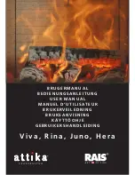
CASTILE PELLET STOVE

O-T L

Tested and 

Listed by

Beaverton

Oregon USA

OMNI-Test Laboratories, Inc.

C

Owner’s Manual

Installation and Operation

CASTILE-MBK
CASTILE-PMH
CASTILE-CLG
CASTILE-CCR

Model: 

HOT! DO NOT TOUCH

SEVERE BURNS MAY RESULT.

CLOTHING IGNITION MAY RESULT.

WARNING

•  Keep children away. 


•  CAREFULLY SUPERVISE children in same room as 

appliance.

•  Alert children and adults to hazards of high 

temperatures.

•  Do NOT operate with protective barriers open or 

removed.

•  Keep clothing, furniture, draperies and other 

combustibles away. 

Glass  and  other  surfaces  are  hot 

during operation and cool down.

DO NOT DISCARD THIS MANUAL

CAUTION

•  Important operating and 

maintenance  instruc-

tions included.

• 

Leave this manual with 

party responsible for use 

and operation.

• 

Read, understand and 

follow  these  instruc-

tions for safe installa-

tion and operation.

DO NOT 

DISCARD

 WARNING

Please read this entire manual 

before installation and use of this 

pellet fuel-burning room heater.  

Failure to follow these instructions 

could result in property damage, 

bodily injury or even death.

• 

Do not store or use gasoline or other flam-

mable vapors and liquids in the vicinity of this 

or any other appliance.

•  Do not overfire - If any external part starts to 

glow, you are overfiring. Reduce feed rate.  

Overfiring will void your warranty.

•  Comply with all minimum clearances to com-

bustibles as specified.  Failure to comply may 

cause house fire.

Check building codes prior to installation.

•  Installation MUST comply with local, regional, state 

and national codes and regulations.

•  Consult local building, fire officials or authorities having 

jurisdiction about restrictions, installation inspection, 

and permits.

CAUTION

Tested and approved for wood pellets and shelled 

field corn fuel only.  Burning of any other type of fuel 

voids your warranty.

CAUTION

Summary of Contents for CASTILE CASTILE-CCR

Page 1: ...follow these instruc tions for safe installa tion and operation DO NOT DISCARD WARNING Please read this entire manual before installation and use of this pellet fuel burning room heater Failure to fol...

Page 2: ...uemment Ne pas connecter cet appareil une chemin e servant un autre appareil Utilisez syst m de ventilation L ou P diam tre 76mm ou 102mm Test ASTM 1509 95 ORD C 1482 M1990 Room Heating Pellet Burning...

Page 3: ...ate Masonry 15 Section 6 Mobile Home 16 Section 7 Appliance Set Up A Outside Air Kit 17 B Leg Leveling System 18 C Top Vent Adapter 18 D Rear Vent Adapter 18 E Log Set Placement 19 F Thermostat Instal...

Page 4: ...obile Home Approved NOTE This installation must conform with local codes In the absence of local codes you must comply with the ASTM E1509 UM 84 HUD ULC ORD C 1482 D Electrical Rating 115 VAC 60 Hz St...

Page 5: ...must maintain the designated air space clearance around the chimney This space around a chimney is necessary to allow natural heat removal from the area Insulation in this space will cause a heat buil...

Page 6: ...nside the Component Pack Inspect all the parts and glass for ship ping damage Contact your dealer if any irregu larities are noticed 3 All safety warnings have been read and fol lowed 4 This Owner s M...

Page 7: ...View Figure 7 1 Top View Figure 7 3 Side View Figure 7 4 Side View with Top Vent Adapter 11 13 16 in 300mm 24 3 4 in 629mm 23 5 8 in 651mm 28 7 16 in 722mm 23 1 4 in 591mm 22 15 16 in 583mm 15 13 16 i...

Page 8: ...to Appliance 2 51 H Side Wall to Flue Pipe 3 76 Alcove Installation Inches Millimeters Minimum Alcove Height 43 1092 Minimum Alcove Side Wall 6 152 Minimum Alcove Width 38 965 Maximum Alcove Depth 36...

Page 9: ...NS A noncombustible oor pro tection extending beneath the ue pipe is required with hori zontal venting or under the Top Vent Adapter with vertical installation Must extend 2 inches 51mm beyond each si...

Page 10: ...ED venting components may be used NO OTHER vent components may be used Substitute or damaged vent components may impair safe operation WARNING B Venting Termination Requirements 1 Termination must exh...

Page 11: ...hart until you reach your altitude above sea level If you fall below the diagonal line 3 or 4 inch 76 to 102mm pipe may be used If it is anywhere above the diagonal line a 4 inch 102mm diam eter pipe...

Page 12: ...ONLY Illustrations diagrams are not drawn to scale Actual installation may vary due to individual design preference A Alcove Figure 12 1 All minimums listed are to a combustible surface Minimum Maxim...

Page 13: ...om the wall Approved for mobile home instal lations Must use 3 or 4 inch 76 102mm L or PL listed pellet venting or listed double wall pipe and a Quadra Fire Outside Air Kit in mobile homes NOTE In Can...

Page 14: ...inch 76 to 102mm L or PL listed pellet venting or listed double wall pipe and Quadra Fire Outside Air Kit in mobile homes Single wall pipe is approved for residential installations only C Vertical D...

Page 15: ...ry Figure 15 1 Figure 15 2 Non combustible Hearth Pad Airtight Cleanout Door Cleanout cover Sheathing 3 in 76mm minimum 1 in 25mm clearance Flashing Fireclay flue liner with airspace Concrete Cap 1 in...

Page 16: ...protection requirements on pages 8 9 for listings to combus tibles and appropriate chimney systems 6 Use silicone to create an effective vapor barrier at the location where the chimney or other compon...

Page 17: ...on cap with second hose clamp 5 Secure termination cap to outside surface 6 Secure trim ring to interior wall Tools Needed Phillips headscrewdriver wire cutters hole saw or jig saw CAUTION Never draw...

Page 18: ...lation Figure 18 5 Figure 18 4 Installing the Top Vent Adapter Top Vent Adapter 3 to 3 inch Rear Exhaust Outlet Use hole on each side as drilling guide Offset Collar 3 to 6 inch Mount with 4 screws Cl...

Page 19: ...e right rear log as shown in Figure 19 1 There is a notch in the bottom of the log for clearance for the thermocouple and thermocouple cover ceramic protection tube 3 Continue placing the last 3 logs...

Page 20: ...dings The thermostat should be mounted on an inside wall and not in direct line with the appliance convection air NOTE If the thermostat is located too close to the appliance you may need to set the t...

Page 21: ...e factory and eld testing has demonstrated shelled eld corn to be an ef cient and very economical fuel We recommend the use of a 50 50 blend of corn and wood pellets The only change in operation is th...

Page 22: ...ed system and allow the appliance to begin dropping pellets The appliance will continue to run as long as the thermostat is calling for heat 6 Once the appliance has ignited let it burn for approximat...

Page 23: ...AUTION WARNING Fire Risk Do NOT operate appliance With appliance door open Firepot oor open Cleaning slide plates open Do NOT store fuel Closer than required clearances to com bustibles to appliance W...

Page 24: ...nting system is clean Make sure front door is closed Replace control box Call light on No re Partially burned fuel in repot Firepot clean out plate not closed Firepot is dirty missed ignition Check th...

Page 25: ...s of vacuum Empty hopper of fuel Use a wet dry vacuum cleaner to remove remaining fuel from hopper including feed tube Check feed chute for obstructions Loosen 2 feed assembly mounting screws and ligh...

Page 26: ...tainless steel baf e from rebox to clean ash from on top of baf e Clean behind rear brick panels Change fuel brand to premium Check that repot clean out plate is fully closed Reduce feed rate using fe...

Page 27: ...n page 28 B General Maintenance 1 Types of Fuel Depending on the type of fuel you are burning will dictate how often you have to clean your repot If the fuel you are burning has a high dirt or ash con...

Page 28: ...ency Monthly or after burning 1 ton of fuel By Homeowner Task A more thorough cleaning is needed to remove the excess ash that is left behind from the use of the cleaning rods for the heat exchanger t...

Page 29: ...15 Soot and Fly Ash Formation Need for Removal in Exhaust Venting System Frequency Yearly or as needed By Quali ed Service Technician Homeowner Task The products of combustion will contain small part...

Page 30: ...of burning fuel caused by poor quality pellet fuel Figure 30 3 shows the correct ame size when good quality premium pellet fuel is burned If the ash buildup exceeds the half way point in the repot IMM...

Page 31: ...d nuts 4 total that is securing the blower to the housing g Remove blower and replace with new blower e Re install in reverse order D Blower Replacement 2 Exhaust Blower Replacement NOTE The convectio...

Page 32: ...lates etc f Re install the ash pan close the ash removal door Re install the side panel and re connect the power a Allow appliance to cool completely b Open doors and locate the latch It is located be...

Page 33: ...river tap the bottom of the rope retainer rod to push it up out of the hole The top end of the rod will slide up Swing the rod toward you from the bottom and remove the rod Repeat for other side c Rem...

Page 34: ...ticipator should be set on the lowest setting available When describing the location of a component it is always AS YOU FACE THE FRONT OF THE APPLIANCE 2 Convection Blower The convection blower is mou...

Page 35: ...auger tube in the center of the appliance and has a red reset button To access it remove the right side panel If the re tries to burn back into the feed system or push exhaust up the feed tube this s...

Page 36: ...RMINAL BLOCK CENTER 2 SCREWS FOR THERMOSTAT WIRES POWER OUTLET FUSE Fuse Red Call Light is located on top of Junction Box behind the Control Box Control Box Vacuum Switch Convection Blower Housing Exh...

Page 37: ...PHL MS ZC 229 1230 54 Face Cast See Service Parts 2 Door Assembly 413 5110 3 Door Latch Assembly 413 5200 4 Hinge Door Female 450 2910 5 Glass Assembly 7001 038 6 Rope Retainer 7001 192 7 Hinge Pin R...

Page 38: ...sh Catcher 39 Snap Disc 1 48 Door Glass Assembly 31 Ash Door Assembly 40 Feed Motor Assembly 49 Brick Left 32 Ash Pan 41 Vacuum Switch 50 Brick Center 33 Igniter Access Plate 42 Top Vent Kit 50 Brick...

Page 39: ...e DVD 413 5130MBK 413 5150PCR 413 5180PMH 413 5140CLG 43 Control Box SRV7005 205 48 Door Assembly Glass Assembly with bottom air wash 413 5110 Door Latch Assembly with Hex Rivnut 413 5200 54 Face Matt...

Page 40: ...Rectangular 7000 166 Item No Accessories Part No Log Set 4 pieces 811 0852 Log Top to cover repot 811 0900 Outside Air Kit 811 0872 Rear Vent Adapter 3 to 3 inches 811 0620 Rear to Top Vent Adapter 3...

Page 41: ...R R R October 11 2005 250 6422D Page 41 Castile Pellet Stove Date of Service Performed By Description of Service E SERVICE AND MAINTENANCE LOG...

Page 42: ...Page 42 250 6422D October 11 2005 R Castile Pellet Stove Date of Service Performed By Description of Service E SERVICE AND MAINTENANCE LOG Cont d...

Page 43: ...omeTechnologiesdiscontinuesthe modeland two 2 years for optional accessories Adjustments regular maintenance cleaning and temporary repairs do not qualify for a service call fee and will not be covere...

Page 44: ...structions included Read understand and follow these instruc tions for safe installation and operation Leave this manual with party responsible for use and operation This product may be covered by one...

Reviews: