manualshive.com logo in svg
background image

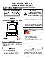
EVOLUTION PELLET INSERT & INSERT KIT 


INSTALLATION & OPERATION MANUAL 

MODEL NUMBERS:     25-EPI     55-SHPEPI     55-TRPEPI 


SAVE THESE INSTRUCTIONS


CAUTION 

Please read this entire manual before installation and use of this pellet fuel-

burning appliance.  Keep children, furniture, fixtures and all combustibles away 

from any heating appliance. 

SAFETY NOTICE 

Failure to follow these instructions can result in property damage, bodily injury 

or even death.  For your safety and protection, follow the installation 

instructions outlined in this manual.  Contact your local building or fire officials 
about restrictions and installation inspection requirements (including permits) in 

your area. 

Rev. 8/2008 

Содержание 25-EPI

Страница 1: ... Keep children furniture fixtures and all combustibles away from any heating appliance SAFETY NOTICE Failure to follow these instructions can result in property damage bodily injury or even death For your safety and protection follow the installation instructions outlined in this manual Contact your local building or fire officials about restrictions and installation inspection requirements includ...

Страница 2: ...information on hand if the phone the factory or your dealer regarding this product IMPORTANT IF YOU HAVE A PROBLEM WITH THIS UNIT DO NOT RETURN IT TO THE DEALER CONTACT CUSTOMER SERVICE 1 800 245 6489 Mobile Home Use This freestanding pellet unit is approved for mobile home or doublewide installation with the outside combustion air hook up See the Installation section of this manual for details pe...

Страница 3: ...aintenance Daily o Important Notes 22 o Daily Ash Removal 23 o Cleaning the Burnpot 24 Bi Weekly o Important Notes 25 o Baffle Removal 26 o Tube Cleaning 26 Monthly o Important Notes 27 o Exhaust Chamber 28 o Venting Pipe 39 Yearly o Important Notes 30 o Exhaust Blower 31 32 o Convection Blower 33 o Hopper Fines 33 o Checking Gaskets 34 Trouble Shooting Guide Troubleshooting 35 36 Replacing Compon...

Страница 4: ...while remaining simple our stoves are designed to perform extremely efficiently helping deliver more heat from less fuel Please look at our vast Help section on our website and call our Customer Service Department at 800 245 6489 if you need any help with your unit We are nearly always able to help walk you through any installation questions repairs problems or other questions that you may have Wi...

Страница 5: ... o 29 1 4 742 95mm Surround Width o 40 0 1016mm Minimum Fireplace Dimensions Min Fireplace Width Front o 36 00 914 4mm Min Fireplace Width Rear o 22 0 558 8mm Min Fireplace Height o 21 0 533 4mm Min Fireplace Depth o 16 0 406 4mm The minimum fireplace dimensions listed may not apply to your specific installation and are for general reference only Use the unit dimensions along with practical knowle...

Страница 6: ...dependent on the type of pellets burned in the stove as such these numbers may vary The maximum heating capacity of this unit can vary greatly based on climate construction style insulation and variety of other factors Use this information in conjunction with a BTU loss calculation for your home to determine if this unit will be sufficient for your needs WARNING Do not store or use gasoline or oth...

Страница 7: ...e insert version of this stove 4 Locate the Rear Hopper Cover Plate Assembly which was included in the insert conversion kit This part comes preassembled with the rear hopper cover plate new hopper lid and hopper lid hinges It also comes predrilled for the required fasteners 5 Lay the Rear Hopper Cover Plate Assembly on the top of the hopper lid be certain the assembly is centered on the stove and...

Страница 8: ...ound side panel the insert side panel and then into the stove body 10 Next slide the top surround panel onto the pre installed sheet metal screws on the top of the Rear Hopper Cover Plate Install two bolts through the pre drilled holes on either side of the surround top panel where it meets the two side panels of the surround 11 Tighten the 1 4 bolts first and then using a 5 16 socket or open end ...

Страница 9: ...e hot during operation CAUTION Keep children away Supervise children in the same room as this appliance Alert children and adults to the hazards of high temperatures Do NOT operate with protective barriers open or removed Keep clothing furniture draperies and other combustibles away Installation MUST comply with local regional state and national codes and regulations Consult local building fire of...

Страница 10: ... ALWAYS install vent pipe in strict adherence with the instructions and clearances included with your venting system DO NOT connect this pellet stove to a chimney flue which also serves another appliance DO NOT install a flue pipe damper or any other restrictive device in the exhaust venting system of this unit ONLY use chimney liners listed for pellet appliance venting do not use galvanized or B ...

Страница 11: ...tion cap from another A FULL chimney relining is required when installing this stove as an insert o For chimneys 15 ft or shorter 3 in pellet liner may be used o For chimneys 15 ft or taller 4 in pellet liner must be used For high altitude installations altitudes greater than 4000 ft this insert must be used with 4 pellet liner only Using 3 liner will restrict air flow to the unit at high altitude...

Страница 12: ... the top plate from sheet metal Use High Temp RTV silicone to seal the top plate and prevent leaks If the liner system is not a Twist Lock design all joints should be secured with three sheet metal screws Seal all joints in the liner using High Temp RTV silicone Secure the outside air pipe to the stove using a hose clamp or other mechanical fastener The outside air pipe may be run to the top of th...

Страница 13: ... hookup must be metal with a minimum thickness of 0209 in 25 gauge mild steel or greater and an inside diameter of approximately 2 0in o All pipe joints and connections should be sealed with pipe clamps or other mechanical means to insure a leak free outside air connection o Long runs of pipe and excessive elbows for outside air should be avoided Due to frictional resistance in pipe any excessive ...

Страница 14: ...a hearth extension pad which is designed and sold specifically for this purpose can be used A hearth extension pad should be U L listed or equivalent and must only be noncombustible Since the majority of the radiant heat from this unit is projected forward the hearth extension pad only serves to keep ashes and sparks from landing on combustible flooring near the unit A hearth rug is NOT an approve...

Страница 15: ...lid switch down with your finger and check to see that the auger is turning Release the hopper lid switch and be certain that the auger stops turning DO NOT PUT YOUR FINGERS IN THE HOPPER OR NEAR THE ROTATING AUGER After about twenty minutes the control board should display E 2 in the two display windows More information on Error Codes can be found in the Error Code section of this manual At this ...

Страница 16: ...is initiated After approximately fifteen minutes the fire should be burning brightly and the S U should disappear from the control board At this point the stove has begun normal operation and the display windows on the control board will remain empty unless the Heat Range or Blower Speed is adjusted Daily Operation Notes Variation in the flame height is normal and may be particularly noticeable on...

Страница 17: ... board should display S d shortly after pressing the button This initiates the shut down sequence and the stove will remain in shut down mode until it has cooled down To increase the heat output of the stove press the Up heat range button The number in the heat range display window will increase signifying that the control board is now adjusting the heat output to your desired level The blower spe...

Страница 18: ...ustomer service and they will diagnose the cause of the false code E 2 When this code is displayed in the control board window it indicates a failure to light Although the stove may have ignited the pellets the control board did not register a high enough temperature to determine the fire was lit If a fire was ignited wait for the unit to cool clean the burnpot and restart the unit E 3 This error ...

Страница 19: ...ee minutes the unit will be OFF when power returns IMPORTANT Do NOT open the hopper lid or the door to the unit during power outage Open the closest outside door and a window to reduce the chance of any combustion byproducts entering the home Wait for the power to be restored and then press the ON button to restart the unit if necessary Caution Shock Hazard Press the Off button and let the applian...

Страница 20: ... will have a small wire jumper installed in it from the factory This jumper bypasses the thermostat and should be saved 3 Loosen the two screws using a small slotted jewelers screwdriver and remove the jumper 4 Insert the two thermostat wires in place of the jumper and retighten the screws 5 Reinstall the back panel and mount the thermostat the control board automatically reads the thermostat and ...

Страница 21: ...n the stove will burn at whatever heat range and blower speed the control board has been set to When the call for heat is gone i e the room is up to temperature the stove will enter the thermostatic shutdown sequence If during the shutdown period the call for heat returns the stove will complete the shutdown cycle before relighting Remember to locate the thermostat near the stove in a central loca...

Страница 22: ...onitor the ash build up in the stove when first operating the unit as well as whenever a different brand of pellets is burned While the amount of ash generated by this unit is not excessive compared to a traditional log burning woodstove keeping the unit clean and free of ash is ESSENTIAL for peak performance and maximum efficiency Ash build up hampers airflow reduces efficiency and can cause a sm...

Страница 23: ... around the burnpot into the ash pan below Use a long handled screwdriver or putty knife to remove any deposits left in the burnpot being careful to remove them from the burnpot and not allow them to filter down into the cradle area Excessive ash build up in the cradle can cause poor stove performance See Cleaning the Burnpot pg 24 Turn the ash pan latch counterclockwise until it releases and slid...

Страница 24: ...or of the stove and remove the burnpot by lifting the front edge first and then simultaneously lifting up and out on the rear of the burnpot WARNING The burnpot can remain HOT long after the fire has gone out so wear protective gloves whenever handling a potentially hot burnpot Once the burnpot is out of the stove use a long handled screwdriver or putty knife as previously mentioned the remove any...

Страница 25: ...ntenance in the first year will help you understand the location of ash build up as well as the necessary intervals between cleanings Although not specifically listed in this section the gaskets and latches on both the main door and ash pan should always be inspected to ensure a proper seal is being made As previously mentioned an airtight seal at all stove openings is crucial to proper operation ...

Страница 26: ...ough the main loading door As soon as the baffle is out of the stove the area where fly ash accumulates on the firebox shelf will be clear The use of a utility vacuum is high recommended because it will prevent fly ash from falling through the exhaust holes and into the exhaust chamber BEFORE replacing the baffle into the stove inspect the heat exchange tubes for fly ash accumulation and if necess...

Страница 27: ... listed in the Weekly Maintenance and Biweekly Maintenance sections Intervals between monthly cleanings will depend on the duration that stove is burning on a daily basis A stove which is operated continuously will need more frequent monthly cleanings than a stove which is used periodically as supplemental heat A good rule of thumb for monthly maintenance is that it should be done each time an ent...

Страница 28: ... quantity of ash build up The ash deposited in the exhaust chamber should be light fluffy grey or white in color and should be no higher than half way up the clean out port o If the ash is dark brown or black it is generally evidence of incompletely pellet combustion o Do NOT allow the ash to accumulate higher than about half way up the cleanout port significant ash accumulation in this area can c...

Страница 29: ... brushed clean Check the termination cap to be certain is not clogged or restricted by any fly ash accumulation After thoroughly cleaning the venting system reseal any disassembled seams with high temperature silicone Part AC RTV3 if applicable to your venting system Inspect seams that were not disassembled to be certain a smoke tight seal is still being made After prolonged use leaks in the venti...

Страница 30: ...WELL AS the steps listed in the Weekly Maintenance and Biweekly Maintenance sections Yearly maintenance should be performed at the end of the burning season Leaving ash and other build up in the stove during the non heating months can lead to premature metal degradation in the stove and venting system Using extra attention to detail and being certain to be very thorough in the end of season cleani...

Страница 31: ...cess the blower Disconnect the venting system from the exhaust blower just enough that you will be able to remove the exhaust blower from the stove Unplug the two wires which connect the stove wiring harness to the exhaust blower using the quick connect plugs Loosen and remove the 5 16 screw on the top of the exhaust blower output connection which holds the thermal sensor to the exhaust blower Loo...

Страница 32: ...ust blower fan blade Inspect the exhaust blower motor for dust accumulation and carefully remove it ensuring that all air cooling holes into the motor are open and free of dust deposits Install the blower and side panel in the reverse order as described above Remember to check the condition of the exhaust blower gasket AND remember to reconnect the thermal sensor to the top of the exhaust blower o...

Страница 33: ...quality of pellets burned in the stove some accumulation of pellet fines and dust is possible in the hopper The lowest part of the auger near the back of the stove is where most fines will accumulate With the stove off and unplugged use a utility vacuum to remove the fines from the auger tube If the fines cannot be removed from the top of the hopper In order to access the combustion blower the uni...

Страница 34: ...ly the gasket needs to be replaced This test should be repeated around the entire gasket perimeter as gaskets will sometimes seal tightly on one side but be worn and seal poorly on another side Perform this test around the entire perimeter of the door hopper lid and ash pan If any area fails the test the entire gasket should be replaced The part number appropriate to the gasket being replaced can ...

Страница 35: ...st blower not operating 1 Loose connection 1 Check control board connection 2 Bad blower 2 Replace blower 3 Bad vacuum sensor 3 Replace vacuum sensor Lazy Fire 1 Bad exhaust blower 1 Inspect and replace blower 2 Excessive pellet moisture 2 Keep pellets dry 3 Excessive ash build up 3 Thoroughly clean unit 4 Low quality pellets 3 Use only PFI premium pellets Blown Fuse 1 Power surge 1 Replace fuse u...

Страница 36: ...ets and restart the stove 2 The hopper lid was left open too long during refueling 2 Keep the hopper lid open for the shortest interval possible when refueling The safety switch stops the auger when the hopper lid is open 3 Component failure 3 An auger motor failure or combustion motor failure can sometimes results in an E 4 code 4 Blower speed is set too high cooling firebox too rapidly 4 Operate...

Страница 37: ...assembly out of the tube enough that the allen set screw which holds the auger to the steel auger coupler can be accessed Loosen this set screw until the auger is free from the auger motor assembly 5 Next remove the four screws which hold the cast iron auger motor coupler to the auger motor using a 5 16 wrench Slide the cast iron auger motor coupler and the steel spacer plate off of the auger moto...

Страница 38: ... the new blower is performed exhaust in reverse of removal remember to reconnect the new blower to the wiring harness Combustion Blower 1 Before beginning any component replacement be certain the unit is unplugged and thoroughly cooled down 2 Remove the unit from the fireplace 3 Disconnect the venting system from the exhaust blower and disconnect the exhaust blower from the stove wiring harness Lo...

Страница 39: ... of removal be absolutely certain the wires and vacuum house are connected according to the wiring diagram in this manual Igniter 1 Before beginning any component replacement be certain the unit is unplugged and thoroughly cooled down 2 Remove the right side panel and the back panel as previously detailed 3 Locate the igniter as shown in the diagram below 4 Disconnect the igniter wiring from the c...

Страница 40: ... This new unit has been painted with High Temperature Paint that should retain its original look for years If the unit should get wet and rust spots appear the spots can be sanded with fine steel wool and repainted It is crucial that only High Temperature Spray Paint is used Part AC MBSP as others may not adhere to the surface or withstand the high temperatures Similarly some brands of paint will ...

Страница 41: ... blow fuse is used on this Control Board NOTE The bottom three control buttons are preset at the factory and are not user adjustable See the Daily Operation section on pages 14 18 of the manual for more instructions on Control Board settings Recommended Heat Ranges Low Burn Heat Range setting 1 Room Air Blower setting 1 Medium Low Heat Range setting 2 3 Room Air Blower setting Medium High Heat Ran...

Страница 42: ...azard Press the Off button and let the appliance completely cool BEFORE unplugging the appliance and beginning any maintenance or component replacement Risk of shock if appliance is not unplugged before service PU CBEP Control Board Diagram ...

Страница 43: ...every stove The ceramic log set dresses up the firebox interior and gives a feeling of a wood fire The log set does not require any maintenance other than the periodic removal of fly ash which can be accomplished with the same utility vacuum used for general cleaning of the unit The log set retains heat long after the fire has gone out so it should always be handled with fire resistance gloves to ...

Страница 44: ...Page 44 ILLUSTRATED PARTS DIAGRAM Auger Motor Assembly Steel Door Assembly ...

Страница 45: ... Motor Collar 14 Steel CA AC Steel Auger Coupler 15 IP 25EP Firebox Baffle 16 PU ECCEP Exhaust Cleanout Covers 17 PU BPCEP Cradle 18 PU BPEP Burnpot 19 CA 40 Steel Door 20 PU AFEP Steel Auger 21 AC GSEP Glass Support Brackets 22 PU SKEP Insert Surround Kit 23 PU SPSEP Insert Side Panel Set 24 PU ITEP Insert Top and Rear Cover Plate 25 PU APEP Ash Pan 26 Glass AC G40 Three Piece Glass Center 27 AC ...

Страница 46: ...amage resulting from over firing will void your warranty 2 This warranty does not apply if damage occurs because of an accident improper handling improper installation improper operation abuse or unauthorized repair made or attempted to be made 3 The manufacturer is not liable for indirect incidental or consequential damages in connection with the product including any cost or expense providing su...

Страница 47: ...as purchases or the factory at our option will perform the warranty service Other Rights This warranty gives you specific legal rights you may also have other rights which may vary from state to state Please Note This warranty is null and void if the attached warranty registration AND a copy of the sales receipt is not returned within thirty 30 days from the date of purchase Warranty is not transf...

Страница 48: ...________________ VIII City_______________________ State________ Zip Code __________ Unit Information Refer to the sticker on the back of the manual or box to complete this section IX Model Number_____________________ Purchase Date _____________ X Purchase Price_____________________ XI Serial Number_____________________ Mfg Date_________________ Purchase Questions How did you first hear about our p...

Страница 49: ...original date of purchase Use any of these three easy ways to send your warranty information in Mailing Address England s Stove Works Inc Customer Service Department P O Box 206 Monroe Virginia 24574 Fax Number 434 929 4810 Twenty four hours a day Online Registration Visit our warranty registration website at http www englanderstoves com warranty warranty html ...

Отзывы: