


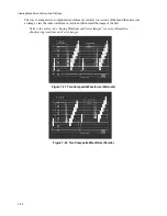


Viewing Waveforms, Vectors, and Pictures
7-15
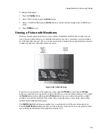
Viewing a Vector
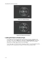
Vectors can be viewed at any time by pressing the
Vector
button (see Figures 7-16 through 7-18).
Pressing the
Vector
button twice shows a vector and a waveform together. Unless you changed it, the
vector color is always yellow so it can be seen easily with a waveform. Note that the vector rose (the
circular graticule for vectors) is simplified when it is displayed with a waveform.
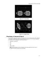
Component signals can also be displayed as vectors. In this case, only the six color boxes are shown
and there is no rose. In addition, phase angle measurements have no meaning in component signals,
and the
Vec. Phase
knob does not operate.
Component signals can be displayed as waveforms with composite signals, but their two vectors
cannot be displayed simultaneously.
To select a vector color:
1.
Press the
Config
button.
2.
Select DISPLAY and then press the
Enter
button.
3.
Select COLOR and then press the
Enter
button.
4.
Select VECTOR COLOR and then press the
Enter
button.
5.
Select any of the three colors and then turn the knob to increase or decrease the color in the vector
trace.
6.
Press the
Clr
Mnu
button to exit.
Once selected, the color is applied to all vector traces until you recall a memory that uses a different
color. To save the color you just selected:
1.
Press the
Config
button.
2.
Using the arrow buttons, select MEMORIES and then press the
Enter
button.
3.
Using the arrow buttons, select STORE MEMORY.
4.
Using the knob, select the desired memory number (1 through 10).
5.
Press the
Down
arrow button to select STORE and then press the
Enter
button.
6.
Press the
Clr
Mnu
button to exit.
Содержание MM-410
Страница 16: ...About This Manual 1 4 Notes...
Страница 34: ...Installation 4 6 Notes...
Страница 48: ...Front Panel Operation 5 14 Notes...
Страница 102: ...Viewing Waveforms Vectors and Pictures 7 30 Notes...
Страница 126: ...Automatic Measurement AVM 510A 9 20 Notes...
Страница 139: ...AVM 510A Option T For Transmission Monitoring 11 5 Figure 11 3 Differential Gain Figure 11 4 Differential Phase...
Страница 148: ...AVM 510A C For Component Measurements 12 4 Notes...
Страница 158: ...Connector Pinouts B 4 Notes...
Страница 162: ...Calibration D 2 Notes...