


AVM-510A Option T (For Transmission Monitoring)
11-9
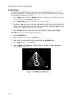
Figure 11-7. ICPM Display (6
°°°°
/Division)
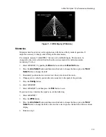
Memories
Memories have been factory set for applications with the most likely mode of operation. It
might be necessary to change some settings in those memories.
For example, memory 9 with ICPM 2
°
/division set to full field display. This needs to be
changed to only view a selected line that has the staircase needed for online transmitter
monitoring. To do so:
1.
Select
MEMORY 9
by pushing the
Blue
button and then the
Mesmnt
button.
2.
Press the
Line Select
button and then rotate the knob to change the line or press the
Field
Select
button to change the field.
3.
Horizontaly position the zero carrier dot at the top of screen to the center.
4.
Change gain to vertically position the zero carrier dot to the peak of the graticule.
5.
Press the
Config
button.
6.
Select
MEMORY
.
7.
Select
MEMORY 9
and then press the
Entr
button to save.
If you don’t know what line the signal is on, do the following:
1.
Select
MEMORY 9
.
2.
Press the
WFM
button.
3.
Press the
Line Select
button and then rotate the knob to change the line or press the
Field
Select
button to change the field to the view the correct signal as the first line of the waveform
display.
4.
Return to step 1.
Содержание MM-410
Страница 16: ...About This Manual 1 4 Notes...
Страница 34: ...Installation 4 6 Notes...
Страница 48: ...Front Panel Operation 5 14 Notes...
Страница 102: ...Viewing Waveforms Vectors and Pictures 7 30 Notes...
Страница 126: ...Automatic Measurement AVM 510A 9 20 Notes...
Страница 139: ...AVM 510A Option T For Transmission Monitoring 11 5 Figure 11 3 Differential Gain Figure 11 4 Differential Phase...
Страница 148: ...AVM 510A C For Component Measurements 12 4 Notes...
Страница 158: ...Connector Pinouts B 4 Notes...
Страница 162: ...Calibration D 2 Notes...