


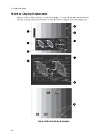


Installation
4-3
DC Control
This 9-pin connector lets you select any of the first four front panel memory locations by grounding
(earthing) any one of the four pins (DC Control). An indication of the selection of one of the first three
memories is given by the grounding of three other pins (refer to the following table).
Pin
Description
1
Recall memory 1
2
Recall memory 2
3
Recall memory 3
4
Recall memory 4
5
Alarm out (AVM-510A)
6
Memory 1 out
7
Memory 2 out
8
Memory 3 out
9
Ground (earth)
Alarm (AVM-510A)
For the AVM-510A, pin 5 (alarm out) is dedicated to an alarm. Each time a screen shows an out-of-
tolorance condition, this pin goes to ground (earth) if MASTER ALARM is enabled and after a delay is
set in the MASTER ALARM DELAY menu option.
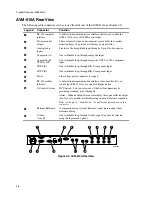
Analog Audio Inputs (AVM-510A)
Provides an input of 4 single-ended audio signals from selected inputs through a 9-pin D-sub
connector.
Pin Number
Description
1
Analog input 1+ (balanced)
2
Analog input 2+ (balanced)
3
Analog input 3+ (balanced)
4
Analog input 4+ (balanced)
5
Ground
6
Analog input 1- (balanced)
7
Analog input 2- (balanced)
8
Analog input 3- (balanced)
9
Analog input 4- (balanced)
Analog inputs 1 through 4 are two-wire inputs.
Содержание MM-410
Страница 16: ...About This Manual 1 4 Notes...
Страница 34: ...Installation 4 6 Notes...
Страница 48: ...Front Panel Operation 5 14 Notes...
Страница 102: ...Viewing Waveforms Vectors and Pictures 7 30 Notes...
Страница 126: ...Automatic Measurement AVM 510A 9 20 Notes...
Страница 139: ...AVM 510A Option T For Transmission Monitoring 11 5 Figure 11 3 Differential Gain Figure 11 4 Differential Phase...
Страница 148: ...AVM 510A C For Component Measurements 12 4 Notes...
Страница 158: ...Connector Pinouts B 4 Notes...
Страница 162: ...Calibration D 2 Notes...