
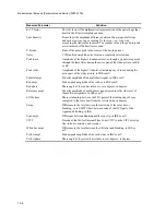

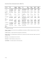


12-1
12
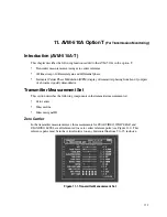
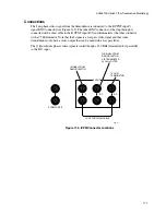
12. AVM-510A-C
(For Component Measurements)
Introduction (AVM-510A-C)
The AVM-510A-C includes a component measurement set and a digital measurement set when an
SDM-550 is interconnected.
Component Measurement Sets (AVM-510A-C)
Setting limits for component signals SMPTE/EBU, Beta, MII, and RGB can only be done when
Input B: is active and is configured for a component signal.
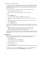
To change the Input B: selection to component:
1.
Press the
Config
button.
2.
Select INPUT and then press the
Entr
button.
3.
Select INPUT B: and then press the
Entr
button several times (or rotate the knob) until the
component system you want appears on the display.
NOTE:
The AVM-510A-C can have different limits for each of the four component signal
standards.
4.
Press the
Clr Mnu
button to exit.
To set the component limits:
1.
Press the
Mesmnt
button.
2.
Select SELECT SET and then press the
Entr
button.
3.
You should now only see one item COMPONENT. Press the
Entr
button to continue.
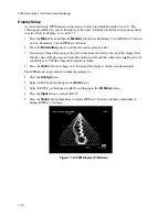
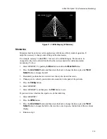
4.
Select MEASURE LINE and then turn the knob to select the line which has the signal. Note that
this might be in the active area or in the vertical interval. You can also switch from one field to
another by turning the knob or by pressing the
Field Select
button.
5.
Select SIGNAL ID and then press the
Entr
button several times to select one of the following:
•
AUTO SIG ID
this signals the AVM-510A-C to determine what the signal is and apply that
measurement set.
•
LIVE VIDEO
this choice shuts off all the parameters except those that are appropriate for live
video measurement.
Содержание MM-410
Страница 16: ...About This Manual 1 4 Notes...
Страница 34: ...Installation 4 6 Notes...
Страница 48: ...Front Panel Operation 5 14 Notes...
Страница 102: ...Viewing Waveforms Vectors and Pictures 7 30 Notes...
Страница 126: ...Automatic Measurement AVM 510A 9 20 Notes...
Страница 139: ...AVM 510A Option T For Transmission Monitoring 11 5 Figure 11 3 Differential Gain Figure 11 4 Differential Phase...
Страница 148: ...AVM 510A C For Component Measurements 12 4 Notes...
Страница 158: ...Connector Pinouts B 4 Notes...
Страница 162: ...Calibration D 2 Notes...