


Operating the MM-410/AVM-510A
6-22
To connect at short distances, you need:
•
A computer running Windows 3.1, 95, 98, or NT with an available serial port
•
A 9-pin serial cable
•
Logbook Software
To configure the AVM-510A for a modem connection:
1.
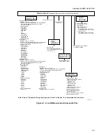
Connect the AVM-510A using the RS-232/Modem port at the rear panel to an available modem
connection (see Figure 3-2).
2.
Press the
Config
button.
3.
Select OTHER and then press the
Enter
button.
4.
Select SERIAL PORTS and then press the
Enter
button.
5.
To set the desired configuration, select MODEM PRINTER PORT.
6.
Press the
Clr Mnu
button to exit.
To configure the AVM-510A for a direct computer connection:
1.
Press the
Config
button.
2.
Select OTHER and then press the
Enter
button.
3.
Select SERIAL PORTS and then press the
Enter
button.
4.
Select COMPUTER SETUP and then press the
Enter
button.
5.
Select BAUD RATE and then select 9600.
6.
Select HANDSHAKING and then select XON/XOFF.
7.
Press the
Clr Mnu
button to exit.
Getting Information To and From the AVM-510A
Besides displaying the waveform of the signal on a picture monitor, the AVM-510A has several other
features in getting information to and from a computer and printer. These include printing a waveform
to a printer, alerting you, with a relay closure, that some measurement value has exceeded its
tolerance, letting you know which memory was selected or selecting a memory with a relay closure,
and the ability to control the AVM-510A with a computer from a remote site.
The method that offers the most flexibility is to connect the AVM-510A to a computer running
Logbook Software. This lets you operate the AVM-510A from a computer as you would from the
front panel.
The second method is reporting. A report is a list of measurements sent directly to a computer, running
any communications program, or sent to a serial printer. Reports can be generated at set intervals,
when there is an error, when errors are cleared, or any combination of these.
Each of these features are explained in the sections that follow.
Содержание MM-410
Страница 16: ...About This Manual 1 4 Notes...
Страница 34: ...Installation 4 6 Notes...
Страница 48: ...Front Panel Operation 5 14 Notes...
Страница 102: ...Viewing Waveforms Vectors and Pictures 7 30 Notes...
Страница 126: ...Automatic Measurement AVM 510A 9 20 Notes...
Страница 139: ...AVM 510A Option T For Transmission Monitoring 11 5 Figure 11 3 Differential Gain Figure 11 4 Differential Phase...
Страница 148: ...AVM 510A C For Component Measurements 12 4 Notes...
Страница 158: ...Connector Pinouts B 4 Notes...
Страница 162: ...Calibration D 2 Notes...