


Operating the MM410/AVM-510A
6-3
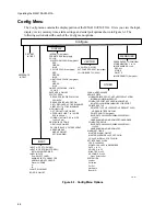
INPUT Sub-Menu
This section describes each of the INPUT sub-menu options. Input A: and Input B: lets you select a
displayed input and the format of the selected input.
INPUT A:
Lets you select either a CPST-1 (Composite) or S-video signal input for display when Input A: is
selected.
INPUT B:
Lets you select the CPST-2 (Composite), SMPTE/EBU, BETA, MII/S, S-video, or GBR signal input
for display when Input B: is selected.
LABEL INPUTS
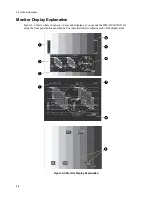
Lets you label the line display (
1
, Figure 5-3) for a selected signal input. If left blank, the signal input
lines display the factory defaults.
CLAMP:
Lets you switch between a slow clamp to see or a fast clamp to remove low frequency components of
a signal.
BOWTIE
Lets you turn on/off a bowtie display. Note that this display is Y minus R-Y paraded with Y minus B-
Y in component waveform and minus B in composite waveform.
DISPLAY Sub-Menu
This section describes each of the DISPLAY sub-menu options.
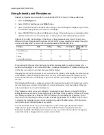
INTENSITY
Lets you see and change the intensity level of a display in the form of a horizontal bar graph.
PERSISTENCE
Lets you see and change the persistence level of a display in the form of a horizontal bar graph.
COLOR
WAVEFORM COLOR
Lets you select and set Red, Green, and Blue horizontal bar graphs for the WAVEFORM display color.
VECTOR COLOR
Lets you select and set Red, Green, and Blue horizontal bar graphs for the VECTOR display color.
GRATICULE COLOR
Lets you select and set Red, Green, and Blue horizontal bar graphs for the GRATICULE display color.
Содержание MM-410
Страница 16: ...About This Manual 1 4 Notes...
Страница 34: ...Installation 4 6 Notes...
Страница 48: ...Front Panel Operation 5 14 Notes...
Страница 102: ...Viewing Waveforms Vectors and Pictures 7 30 Notes...
Страница 126: ...Automatic Measurement AVM 510A 9 20 Notes...
Страница 139: ...AVM 510A Option T For Transmission Monitoring 11 5 Figure 11 3 Differential Gain Figure 11 4 Differential Phase...
Страница 148: ...AVM 510A C For Component Measurements 12 4 Notes...
Страница 158: ...Connector Pinouts B 4 Notes...
Страница 162: ...Calibration D 2 Notes...