31
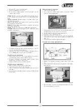
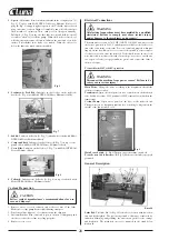
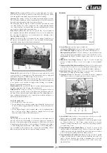
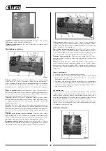
4. Set Selector lever (D, Fig.18) to correct position (neutral).
5. Engage the half nut lever (A, Fig.18).
6. Make a test cut with scrap material and check results before cutting
regular material.
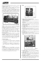
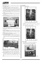
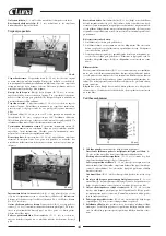
Compound Slide.
The compound slide (C, Fig.18) is located on top of the
cross slide and can be rotated 360°. There are calibrations in degrees (B,
Fig.18) below the rest to assist in placement of the compound to the desi-
red angle.
Gib Adjustments.
After a period of time some of the moving components
may need to be adjusted due to wear.
Saddle.
Turn gib screws on either side of the saddle at the rear to adjust
the drag on the saddle.
Cross Slide.
Turn gib screws in the front and rear of the gib to adjust the
drag of the cross slide.
Compound Slide
. Turn gib screws to adjust the drag of the compound sli-
de.
Tailstock Off-Set.
Follow the procedure below to off-set the tailstock to
cut shallow tapers:
Fig. 22
Fig. 21
Fig. 19
Fig. 20
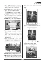
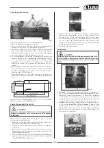
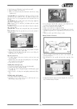
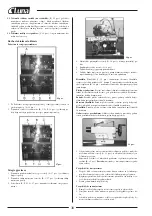
1. Loosen tailstock in position by lowering locking handle (A, Fig.19)
and loosening hexagon head eccentric shaft.
2. Alternately loosen and tighten front and rear set screws (B, Fig.19).
Note:
Front side set screw shown.
Removing Gap Section
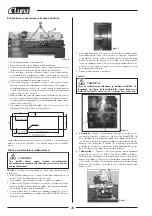
1. To remove the gap section, remove four hex socket cap screws, and
two hex cap bolts.
2. Tighten the hex nuts on the tapered alignment pins to loosen the pins.
Once loosened, they can be removed.
3. Gap section can now be removed.
Installing Removable Gap Section
1. Clean the bottom and the ends of the gap section thoroughly.
2. Set gap section in place and align the ends.
3. Loosen the nuts on the locating pins and push down through the gap in
to the lathe bed.
4. Replace four hex socket cap screws and tighten alternately until all are
snug.
Belt Replacement and Adjustment
1. Disconnect machine from the power source.
2. Open end gear cover, remove lower rear cover and lower side cover.
This will expose the motor and V-belts.
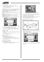
3. Loosen hex nut (A, Fig.20). Place scrap piece of wood under motor to
act as lever. Lift motor up and block temporarily.
4. Remove belts. Install new belts onto pulleys.
5. Lift up on motor and remove temporary blocking.
6. Tension belts by loosening nut (B, Fig.20) and tighten nut (A, Fig.20)
until light finger pressure causes approximately 3/4" deflection on each
belt.
7. Install covers and connect lathe to the power source.
Aligning Tailstock to Headstock
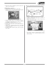
1. Fit a 12" ground steel bar between centers of the headstock and
tailstock (See Fig.21).
2. Fit a dial indicator to the top slide and traverse the center line of the
bar.
3. If adjustment is needed, align the tailstock using the off-set screws (A,
Fig. 22) until the tailstock is aligned.
Содержание 20758-0580
Страница 2: ......
Страница 73: ...71 Stand Assembly...
Страница 76: ...74 Brake Assembly...
Страница 78: ...76 Bed Assembly...
Страница 81: ...79 Headstock Assembly I...
Страница 84: ...82 Headstock Assembly II...
Страница 87: ...85 Headstock Assembly III...
Страница 89: ...87 Headstock Assembly IV...
Страница 91: ...89 Change Gear Box Assembly I...
Страница 93: ...91 Change Gear Box Assembly II...
Страница 95: ...93 Quick Change Gear Box I...
Страница 98: ...96 Quick Change Gear Box II...
Страница 100: ...98 Quick Change Gear Box III...
Страница 102: ...100 Apron Assembly I...
Страница 105: ...103 Apron Assembly II...
Страница 108: ...106 Apron Assembly III...
Страница 110: ...108 Carriage Assembly...
Страница 113: ...111 Carriage Stop Assembly...
Страница 115: ...113 Four Way Tool Post...
Страница 117: ...115 Tailstock Assembly I...
Страница 119: ...117 Tailstock Assembly II...
Страница 121: ...119 Steady Rest Assembly...
Страница 123: ...121 Follow Rest Assembly...
Страница 125: ...123 Coolant Work Light Assembly...
Страница 130: ...128 Wiring Diagram...
Страница 138: ......
Страница 139: ......

