29
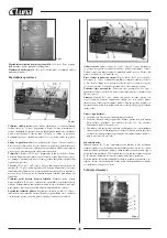
Headstock.
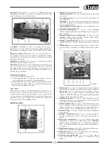
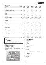
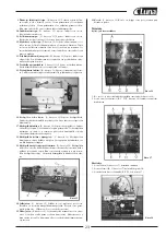
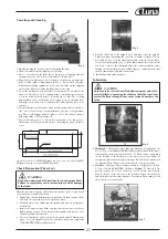
The headstock (B, Fig. 10) is cast from high grade, low vibra-
tion cast iron. It is bolted to the bed by four hex socket cap bolts. In the
head, the spindle is mounted on precision taper roller bearings.
Carriage.
The carriage (C, Fig. 10) is made from high quality cast iron.
The cross-slide is mounted on the carriage and moves on a dovetailed sli-
de which can be adjusted for play by means of the gibs.
The compound slide (D, Fig. 10), which is T-slotted, and mounted on the
cross slide (E, Fig. 10), can be rotated 360°. The compound slide and the
cross slide travel in a dovetailed slide and have adjustable gibs. A four
way tool post is fitted on the compound slide.
Four Way Tool Post.
The four way tool post (F, Fig. 10) is mounted on
the compound slide and allows a maximum of four tools to be mounted at
the same time. Remember to use a minimum of two clamping screws
when installing a cutting tool.
Apron.
The apron (G, Fig. 10) is mounted to the carriage. Quick travel of
the apron is accomplished by means of a bed mounted rack and pinion,
operated by a hand wheel on the front of the apron.
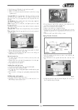
Fig. 13
Fig. 12
Fig. 11
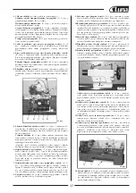
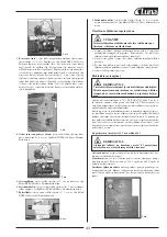
Tailstock.
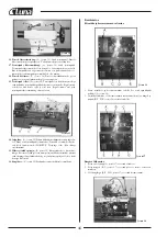
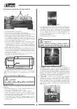
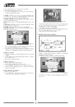
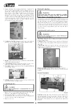
The tailstock (A, Fig. 11) slides on a v-way and can be locked
at any location by a clamping lever. The tailstock has a heavy duty quill
with a Morse Taper #4, or Morse Taper #5 (18” models).
Leadscrew and Feed Rod.
The leadscrew (B, Fig. 11) and feed rod (C,
Fig. 11) are mounted on the front of the machine bed. They are connected
to the gearbox at the left and are supported by bearings on both ends.
Both are equipped with shear pins.
Feed Gear Box.
The gear box (D, Fig. 11) is made from high quality cast
iron and is mounted to the left side of the machine bed.
Steady Rest.
The steady rest (F, Fig. 11) serves as a support for shafts on
the free tailstock end. The steady rest is mounted on the bedway and secu-
red from below with a bolt, nut and locking plate. The sliding fingers re-
quire continuous lubrication at the contact points with the workpiece to
prevent them from premature wear.
To set the steady rest:
1. Loosen three hex socket cap screws.
2. Loosen knurled screw and open sliding fingers until the steady rest can
be moved with its fingers around the workpiece. Secure the steady rest
in position.
3. Set the fingers snugly to the workpiece and secure by tightening three
hex socket cap screws. Fingers should be snug but not overly tight.
Lubricate sliding points with lead based grease.
Follow Rest
The traveling follow rest (E, Fig. 11) is mounted on the saddle and fol-
lows the movement of the turning tool. Only two fingers are required as
the place of the third is taken by the turning tool. The follow rest is used
for turning operations on long, slender workpieces. It prevents the workpi-
ece from flexing under the pressure of the cutting tool. The sliding fingers
are set similar to the steady rest, free of play, but not binding. Always
lubricate adequately with lead based grease during operation.
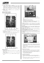
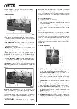
Controls
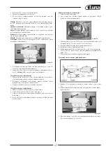
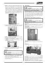
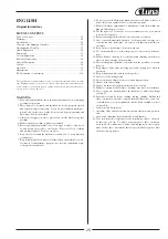
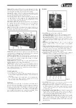
1. Control Panel:
Located on front of headstock.
Coolant On-Off Switch:
(A, Fig.12) turns coolant pump on and off.
Power Indicator Light:
(D, Fig.12) Lit whenever lathe has power.
Emergency Stop Switch:
(C, Fig.12) Depress to stop all machine fun-
ctions. (Caution: Lathe will still have power). Twist clockwise to reset.
Jog Switch:
(B, Fig.12) Quickly depress and release to rotate the
spindle.
2. Headstock Gear Change Levers:
(F, Fig.12) Located on front top
portion of headstock. Move levers left, or right to desired spindle
speed.
3. Leadscrew/Feed Rod Directional Lever:
(E, Fig.12) Located on front
of headstock at left and lower section. Changing knob changes direc-
tion of feed. (Caution: Do not move knob while machine is running.)
4. Feed/Lead Selector Lever:
(H, Fig.12) Located on front of headstock.
Used whenever setting up for threading or feeding.
5. Compound Lock:
(not shown) Lever located on back of compound
slide. Turn clockwise to lock and counter-clockwise to unlock.
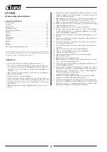
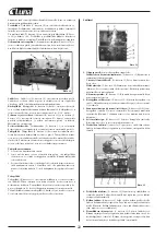
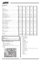
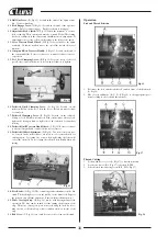
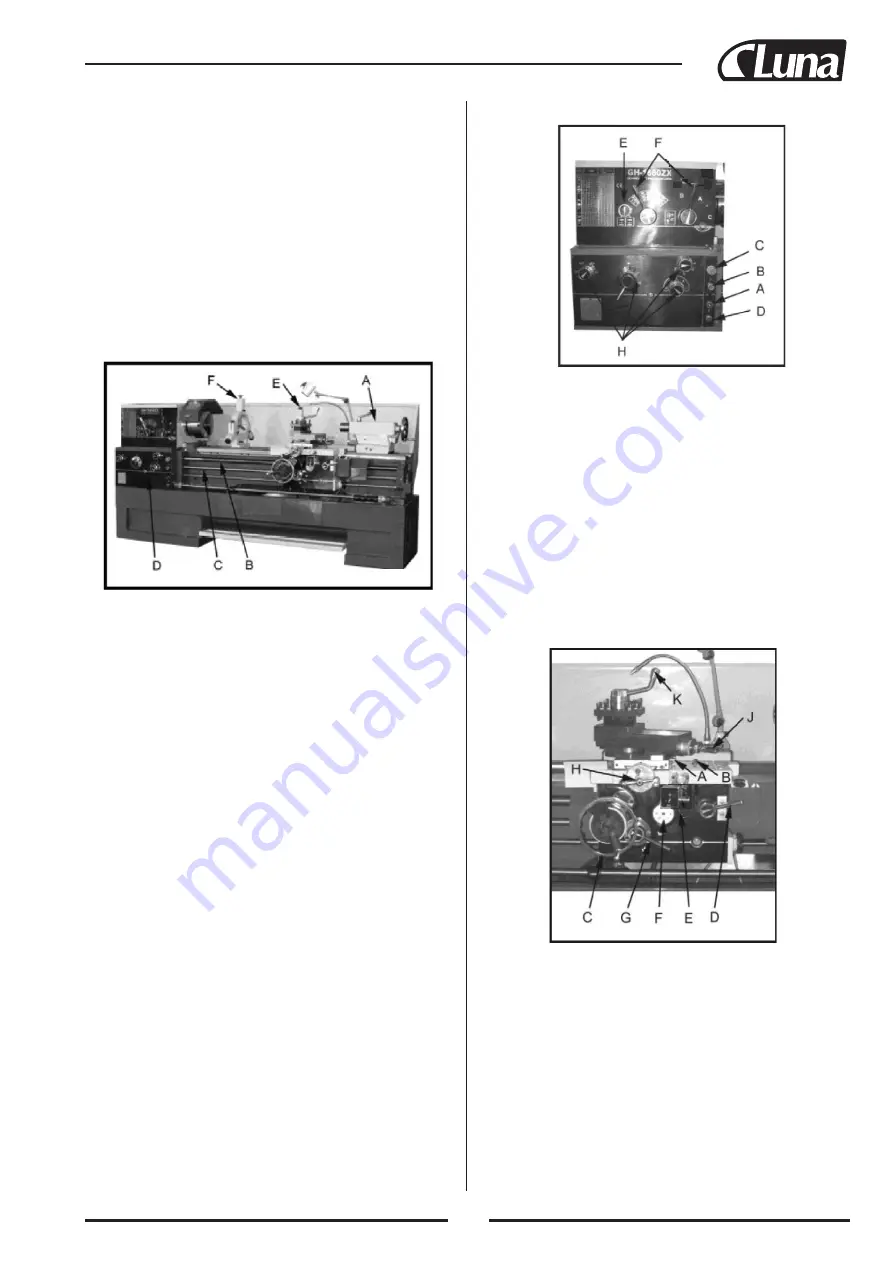
6. Cross Slide Lock:
(A, Fig.13) Lever located on left side of cross slide.
Turn clockwise to lock and counter-clockwise to unlock.
7. Carriage Lock:
(B, Fig.13) Lock handle located on top right of carria-
ge. Turn clockwise to lock. Turn counter-clockwise to unlock.
(Caution: Carriage lock must be loose before moving carriage or dama-
ge to lathe may occur.)
8. Longitudinal Traverse Hand Wheel:
(C, Fig.13) Located on the
apron assembly. Rotate hand wheel clockwise to move the apron as-
sembly toward the tailstock (right). Rotate the wheel counter-clockwise
to move the apron assembly toward the headstock (left).
9. Longitudinal/Cross Feed Selector Lever:
(E, Fig.13) Can be pushed
to upper, middle and lower three positions. Push the lever up, cross
feed is effected. Push the lever down, longitudinal feed is effected.
When the lever is in the middle position, screws can be cut by enga-
ging the half nut.
Содержание 20758-0580
Страница 2: ......
Страница 73: ...71 Stand Assembly...
Страница 76: ...74 Brake Assembly...
Страница 78: ...76 Bed Assembly...
Страница 81: ...79 Headstock Assembly I...
Страница 84: ...82 Headstock Assembly II...
Страница 87: ...85 Headstock Assembly III...
Страница 89: ...87 Headstock Assembly IV...
Страница 91: ...89 Change Gear Box Assembly I...
Страница 93: ...91 Change Gear Box Assembly II...
Страница 95: ...93 Quick Change Gear Box I...
Страница 98: ...96 Quick Change Gear Box II...
Страница 100: ...98 Quick Change Gear Box III...
Страница 102: ...100 Apron Assembly I...
Страница 105: ...103 Apron Assembly II...
Страница 108: ...106 Apron Assembly III...
Страница 110: ...108 Carriage Assembly...
Страница 113: ...111 Carriage Stop Assembly...
Страница 115: ...113 Four Way Tool Post...
Страница 117: ...115 Tailstock Assembly I...
Страница 119: ...117 Tailstock Assembly II...
Страница 121: ...119 Steady Rest Assembly...
Страница 123: ...121 Follow Rest Assembly...
Страница 125: ...123 Coolant Work Light Assembly...
Страница 130: ...128 Wiring Diagram...
Страница 138: ......
Страница 139: ......

