9
luminancebrands.com
Please contact 1-800-777-4440 for further assistance
ETL Model No.: HF1161
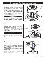
7"
EYE SCREW
OUTLET BOX
Figure 12
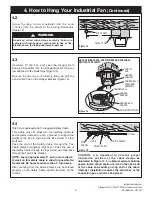
4.2
Screw the Eye Screw (supplied) into the Joist
7-inches from the center of the Ceiling Outlet Box
(Figure 12).
Read and follow instructions carefully. Failure to
comply with instructions could result in risk of fire,
electric shock, fan falling and injury to persons.
WARNING
!
4. How to Hang Your Industrial Fan
(Continued)
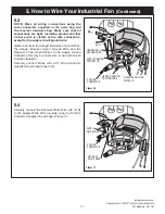
4.3
Carefully lift the Fan and seat the Hanger Ball/
Downrod Assembly into the Hanger Bracket that was
just attached to the Outlet Box (Figure 13).
Be sure the Groove in the Ball is lined up with the
Anti-rotation Tab on the Hanger Bracket (Figure 13).
NOTE: CEILING COVER, SUPPLY WIRES AND FAN WIRES
OMITTED FOR CLARITY.
OUTLET
BOX
HANGER
BRACKET
HANGER BALL/
DOWNROD
ASSEMBLY
HANGER
BRACKET
HANGER BALL
HANGER BALL
GROOVE
ANTI-ROTATION TAB
Figure 13
4.4
This Fan is equipped with the required Safety Cable.
This Cable must be affixed to the building structure
and securely clamped in such a manner to support the
weight of the Fan in the event the Eye Screw or other
parts fail.
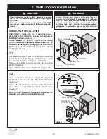
Pass the end of the Safety Cable through the Two
Cable Clamps (supplied) (Figure 14). Pass the end of
the Safety Cable through the Eye Screw and then back
through the Two Cable Clamps.
NOTE: Leave approximately 3” but no more than 5”
of slack on this safety cable to allow for possible fan
movement. Do not exceed more than 5” total slack.
After verifying that the Cable Clamps are positioned
properly on the Safety Cable, tighten the Nuts on the
U-bolts.
CAUTION: It is important to note the proper
installation position of the cable clamps as
illustrated in Figure 14. To obtain maximum holding
power, install U-bolt section of clip on the short end
of the cable and saddle on long end of the cable.
Improper installation reduces the efficiency of the
connection by as much as 40 percent.
EYE
SCREW
CABLE CLAMP
TO FAN
U-BOLT
SAFETY CABLE
Figure 14

