17
luminancebrands.com
Please contact 1-800-777-4440 for further assistance
ETL Model No.: HF1161
7. Wall Control Installation
(Continued)
ON/OFF SWITCH
(pulled out to the OFF position)
OFF
Figure 28
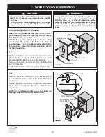
7.3
Before installing the Supplied Wall Control, place the
Wall Control in the Power “OFF” Mode by pulling the
“ON/OFF” Switch out, located at the bottom of the Wall
Control (Figure 28).
Check to see that all connections are tight and that no
bare wires are visible at the wire connectors.
WARNING
!
Do not connect any neutral (white) wire to this control.
Incorrect wiring will damage this control.
WARNING
!
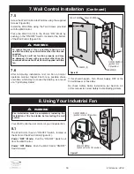
7.4
Securely connect a P2 Wire Connector (supplied with
the wall control) to the Wall Control Black (AC IN L)
Wire and the Wall Box “HOT” Wire (Figure 29).
Securely connect a P2 Wire Connector (supplied with
the wall control) to the Wall Control Black (TO MOTOR
L) Wire and the Wall Box “LOAD” Wire (Figure 29).
Securely connect a P2 Wire Connector (supplied with
the wall control) to the Wall Control Green Ground Wire
and the Wall Box Bare Copper or Green Ground Wire
(Figure 29).
Leave the Wall Control in Power “OFF” Mode until Fan
installation is completed (Figure 29).
WALL CONTROL
WALL BOX
BLACK
BLACK "LOAD"
BARE COPPER
OR GREEN
GREEN
BLACK
P2 WIRE CONNECTOR
ON/OFF SWITCH
(pulled out to OFF position)
OFF
AC IN L
TO MOTOR L
BLACK "HOT"
G
Figure 29

