background image

25

luminancebrands.com

Please contact 1-800-777-4440 for further assistance

ETL Model No.: HF1161

Luminance Brands Ceiling Fan Product Limited Warranty

What The Limited Warranty Covers:

This limited warranty is offered by Luminance Brands (“Luminance Brands” or “our” or “we” or “us”) to the original purchaser (“you” or “your”) of a consumer or industrial Luminance 

Brands ceiling fan product including its motor and the other components, and accessories of a consumer or industrial Luminance Brands ceiling fan product sold separately 

(“Luminance Brands Ceiling Fan Product(s)”) against defects in workmanship and materials, subject to the exclusions described below.
What The Limited Warranty Period Of Coverage Is:

All limited warranty periods herein begin on the date of original Luminance Brands Ceiling Fan Product purchased by You. 

This limited warranty covers the Luminance Brands consumer Ceiling Fan Product motor for the lifetime of the original purchaser’s ownership when operated in accordance with Your Luminance 

Brands Ceiling Fan Product Owner’s Manual or other instructions provided by Luminance Brands to You with the Luminance Brands consumer Ceiling Fan Product. 

This limited warranty covers the Luminance Brands Industrial Ceiling Fan Product motor for five years from the date of purchase of Your Luminance Brands Industrial Ceiling Fan Product 

(when operated in accordance with Your Luminance Brands Ceiling Fan Product Owner’s Manual or other instructions provided by Luminance Brands to You with the Luminance Brands 

Industrial Ceiling Fan Product).

This limited warranty covers the Luminance Brands Ceiling Fan Product LED drivers and LED arrays component or accessory LED drivers and LED arrays for a period of five (5) years. 

All other components of the Luminance Brands Ceiling Fan Product certified as ENERGY STAR® including motor electronics are covered by this limited warranty for a period of three (3) years. 

All other components and accessories of the Luminance Brands Ceiling Fan Product including motor electronics are covered by this limited warranty for a period of one (1) year. 
No Other Express or Implied Warranty Applies:

THE LIMITED WARRANTIES PROVIDED ABOVE ARE THE SOLE AND EXCLUSIVE WARRANTIES PROVIDED BY LUMINANCE BRANDS TO YOU FOR YOUR Luminance Brands Ceiling 

Fan Product, AND ARE IN LIEU OF ALL OTHER WARRANTIES, WRITTEN OR ORAL, EXPRESS OR IMPLIED, WHETHER ARISING BY OPERATION OF LAW OR OTHERWISE, WHETHER 

OR NOT THE PURPOSE HAS BEEN DISCLOSED AND WHETHER OR NOT THE Luminance Brands Ceiling Fan Product HAS BEEN SPECIFICALLY DESIGNED OR MANUFACTURED 

FOR YOUR USE OR PURPOSE. LUMINANCE BRANDS HEREBY DISCLAIMS ANY AND ALL IMPLIED WARRANTIES, INCLUDING WITHOUT LIMITATION, IMPLIED WARRANTIES OF 

MERCHANTABILITY OR FITNESS FOR A PARTICULAR PURPOSE. 
How You Can Receive Warranty Service:

You must be the original purchaser and have proof of Your purchase of Luminance Brands Ceiling Fan Product from an authorized Luminance Brands Dealer to obtain Your remedy under 

this limited warranty. You can return Your Luminance Brands Ceiling Fan Product to an authorized Luminance Brands Dealer, or You can call Luminance Brands Customer Service at 

1-800-777-4440 to obtain a return authorization and service identification tag.  In order for Us to confirm that Your Luminance Brands Ceiling Fan Product is still under warranty, please retain 

Your receipt or other proof of purchase and have that information readily available when returning Your Luminance Brands Ceiling Fan Product to Your place of purchase, or upon calling 

Luminance Brands Customer Service. If You call Luminance Brands Customer Service, prior to Your call, please be prepared to provide all model numbers shown on Your Luminance Brands 

Ceiling Fan Product. Once We have processed your return authorization request, We will provide You with a postage paid return label which should be affixed to the Luminance Brands Ceiling 

Fan Product package You ship. The return label will be sent to the mailing address You provide to Us by phone.
What We Will Do To Correct Problems:

If the defect is covered by this limited warranty, Luminance Brands will repair or replace the applicable Luminance Brands Ceiling Fan Product at no charge to You. If repair of the 

Luminance Brands Ceiling Fan Product is not practical or possible within a reasonable time and no replacement Luminance Brands Ceiling Fan Product can be provided, Luminance Brands will 

refund You the actual purchase price of Your Luminance Brands Ceiling Fan Product. We will ship the repaired or the replacement Luminance Brands Ceiling Fan Product to You at no charge, 

but You are responsible for all costs of removal and reinstallation of Your Luminance Brands Ceiling Fan Product.
What Is Not Covered under the Limited Warranty:

This limited warranty does not extend to and expressly excludes:

•  The glass globes and light bulbs of Your Luminance Brands Ceiling Fan Product,

•  Any costs or fees associated with the labor, including electrician’s fees, required to install, remove, repair or replace a fan or any fan components or accessories.

•  Loss or damage to the Luminance Brands Ceiling Fan Product motor or any Luminance Brands Ceiling Fan Product component or Luminance Brands Ceiling Fan Product accessory caused 

  by normal wear and tear, rather than due to defects in materials or workmanship,

•  Loss or damage resulting from conditions beyond our reasonable control, including without limitation, unforeseeable operating environmental conditions, repairs not made at Our factory or 

  authorized service center, use of parts or accessories not provided to You as part of this warranty by Our factory or authorized service center, mishandling, unreasonable use, misuse, abuse, 

  modifications or other damage caused by You or a third party to your Luminance Brands Ceiling Fan Product while not in Our possession,

•  Loss or damage resulting from improper installation, or other failure to comply with instructions in Your Owner’s Manual including but not limited to Luminance Brands Ceiling Fan Products 

  installed in unintended industrial or residential applications.

•  Luminance Brands Ceiling Fan Product purchases from unauthorized Luminance Brands Dealers.
This limited warranty is deemed null and void upon the occurrence of either of the following events:
•  You as the original purchaser cease to own the Luminance Brands Ceiling Fan Product, or

•  The Luminance Brands Ceiling Fan Product is moved from its original point of installation.

This limited warranty is only valid within the 50 United States, the District of Columbia, and Canada. No other written or oral warranties apply, and no employee, agent, dealer or other person is 

authorized to give any warranties on behalf of Us.
Limitation of Liability:

REPAIR, REPLACEMENT OR A REFUND ARE THE EXCLUSIVE REMEDIES AVAILABLE TO YOU UNDER THIS LIMITED WARRANTY. TO THE EXTENT PERMITTED BY LAW, 

IN NO EVENT SHALL LUMINANCE BRANDS OR ANY LUMINANCE BRANDS AUTHORIZED DEALER BE LIABLE FOR ANY INCIDENTAL, SPECIAL, 

INDIRECT, OR CONSEQUENTIAL DAMAGES, INCLUDING ANY ECONOMIC LOSS, WHETHER RESULTING FROM NONPERFORMANCE, USE, MISUSE 

OR INABILITY TO USE THE Luminance Brands Ceiling Fan Product OR FOR THE NEGLIGENCE OF LUMINANCE BRANDS OR A LUMINANCE BRANDS AUTHORIZED 

DEALER. LUMINANCE BRANDS SHALL NOT BE LIABLE FOR DAMAGES CAUSED BY DELAY IN PERFORMANCE AND IN NO EVENT, REGARDLESS OF THE FORM 

OF THE CLAIM OR CAUSE OF ACTION (WHETHER BASED IN CONTRACT, INFRINGEMENT, NEGLIGENCE, STRICT LIABILITY, OTHER TORT OR OTHERWISE), 

SHALL LUMINANCE BRANDS’ OR ANY LUMINANCE BRANDS AUTHORIZED AGENT’S LIABILITY TO YOU OR ANY INDIVIDUAL USING THE Luminance Brands Ceiling Fan Product 

EXCEED THE PRICE PAID BY THE ORIGINAL OWNER FOR THE Luminance Brands Ceiling Fan Product. The term “consequential damages” shall include, but not be limited to, loss of 

anticipated profits, business interruption, loss of use or revenue, cost of capital or loss or damage to property or equipment. 
Dispute Resolution:

In the event of any dispute INCLUDING, BUT NOT LIMITED TO, BREACH OF CONTRACT, BREACH OF WARRANTY, CLAIMS BASED IN TORT, NEGLIGENCE, PRODUCT LIABILITY, 

FRAUD, MARKETING, STATE OR FEDERAL REGULATIONS, ANY CLAIMS REGARDING THE ENFORCEABILITY OF THIS LIMITED WARRANTY, AND THE WAIVER OF CLASS ACTION 

TRIALS between You and Luminance Brands, either party may choose to resolve the dispute by binding arbitration, as described below, instead of in court. THIS MEANS IF EITHER YOU OR 

LUMINANCE BRANDS CHOOSE BINDING ARBITRATION, NEITHER PARTY SHALL HAVE THE RIGHT TO LITIGATE SUCH CLAIM IN COURT OR HAVE A JURY TRIAL. DISCOVERY 

AND APPEAL RIGHTS ARE LIMITED IN BINDING ARBITRATION. You and Luminance Brands agree that the proper venue if Arbitration is not so chosen by You or Luminance Brands of all 

actions arising in connection herewith shall be only in the state of Ohio and the parties agree to such jurisdiction. 
CLASS ACTION WAIVER: BINDING ARBITRATION MUST BE ON AN INDIVIDUAL BASIS. THIS MEANS NEITHER YOU NOR LUMINANCE BRANDS MAY JOIN OR CONSOLIDATE 

CLAIMS IN ARBITRATION BY OR AGAINST OTHERS, OR LITIGATE IN COURT OR ARBITRATE ANY CLAIMS AS A REPRESENTATIVE OR MEMBER OF A CLASS OR IN A PRIVATE 

ATTORNEY GENERAL CAPACITY.
ADMINISTRATION OF ARBITRATION: The binding arbitration must be administered by the American Arbitration Association (“AAA”) in accordance with its Commercial Arbitration Rules and/

or Supplementary Procedures for Consumer-Related Disputes (including proceedings to mitigate costs of travel). This binding arbitration is governed by the Federal Arbitration Act (“FAA”) 

(9 USC §1, et. seq.) and will govern the interpretation and enforcement. The binding arbitration shall be held at a location determined by AAA or at such other location as mutually agreed. 

In addition to the terms stated above, the following will apply to the binding arbitration: (1) the arbitrator, and not any federal, state, or local court or agency, will have exclusive authority 

to resolve any dispute relating to the interpretation applicability, enforceability or formation of this agreement including any claim that all or any part of this agreement is void or voidable; 

(2) the arbitrator shall apply Ohio law consistent with the FAA.
How State and Provincial Law Relates To The Warranty:

Some states and provinces do not allow the exclusion or limitation of incidental or consequential damages so the above exclusion or limitation may not apply to You. This limited warranty gives 

you specific legal rights, and You may also have other rights which vary from state to state or province to province.

Содержание HF1161BQ00

Страница 1: ...ESE INSTRUCTIONS 1 800 777 4440 www luminancebrands com Questions problems missing parts Before returning to the store Call Customer Service 60 DC Industrial Fan Damp Location Owner s Manual 10 MIN TO...

Страница 2: ...th the outlet box Most outlet boxes commonly used for support of light fixtures are not acceptable for fan support and may need to be replaced Consult a qualified electrician if in doubt 4 Always prop...

Страница 3: ...r replacement parts before proceeding NOTE Intermixing blades between fans can cause excessive wobble Keep blades in original sets of three 1 2 Remove the Fan Motor Assembly from the protective plasti...

Страница 4: ...need to be replaced Consult a qualified electrician if in doubt WARNING Turning off wall switch is not sufficient To avoid possible electrical shock be sure electricity is turned off at the main fuse...

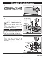
Страница 5: ...emblies Tighten each Blade Screw to secure each Blade Assembly to the Motor Housing SET SCREWS 2 MOTOR YOKE ALLEN WRENCH Figure 3 3 3 Using the Set Screw Wrench supplied remove the Two Set Screws from...

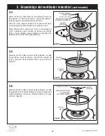
Страница 6: ...or Wires and the Safety Cable through the Hanger Ball Downrod Assembly and seat the Downrod in the Motor Yoke Figure 6 MOTOR COVER 8 EXTERNAL TOOTH LOCKWASHER 8 32 x 1 4 PAN HEAD SCREW Figure 4 3 4 Se...

Страница 7: ...2 ALLEN WRENCH HANGER BALL DOWNROD ASSEMBLY Figure 8 3 8 Reinstall the previously removed Two 5 16 18 Set Screws in the Motor Yoke Figure 8 While pulling up on the Hanger Ball securely tighten both S...

Страница 8: ...upport and may need to be replaced Consult a qualified electrician if in doubt WARNING 4 1 Securely attach the Hanger Bracket to the Outlet Box using the Two Screws supplied with the Outlet Box Figure...

Страница 9: ...AB Figure 13 4 4 This Fan is equipped with the required Safety Cable This Cable must be affixed to the building structure and securely clamped in such a manner to support the weight of the Fan in the...

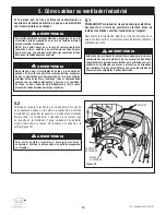
Страница 10: ...wer to the Branch Circuit at the Circuit Breaker or Fuse Box before attempting to Wire the Ceiling Fan 5 How to Wire Your Industrial Fan To avoid possible electrical shock be sure electricity is turne...

Страница 11: ...including ground and that no bare wire is visible at the wire connectors except for the supply circuit ground wire Gather and twist the Hanger Ball Green Ground Wire the Hanger Bracket Green Ground W...

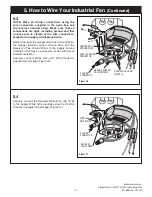
Страница 12: ...CONNECTOR T O M O T O R W T O M O T O R U T O M O T O R V G G G G A C I N N RECEIVER BLACK WIRE SUPPLY BLACK WIRE A C I N L Figure 18 P2 WIRE CONNECTOR T O M O T O R W T O M O T O R U FAN MOTOR GREY W...

Страница 13: ...OR G G G G A C I N N A C I N L TO MO TO R V RECEIVER BROWN WIRE FAN MOTOR BROWN WIRE TO M O TO R W TO MOTOR U Figure 20 5 8 Securely connect the Receiver Blue Wire TO MOTOR W to the Fan Motor Blue Wir...

Страница 14: ...GREY HANGER BALL GREEN WIRE GROUND FROM HANGER BALL TWO CONDUCTOR CABLE WITH GROUND BLACK HOT WHITE SUPPLY GROUND TO 120 VOLT SUPPLY WHITE BLUE GREY BLUE GREEN WIRE GROUND FROM HANGER BRACKET HANGER...

Страница 15: ...ft the Ceiling Cover up to the Threaded Studs and turn until Studs protrude through the Ceiling Cover Holes Figure 25 Secure the Ceiling Cover in place by sliding a Lockwasher over each of the Threade...

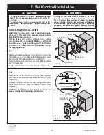
Страница 16: ...including ground and that no bare wire is visible at the wire connectors except for the ground wire 7 1 Disconnect Electrical Power to the Branch Circuit at the Circuit Breaker or Fuse Box before att...

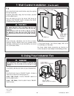
Страница 17: ...damage this control WARNING 7 4 Securely connect a P2 Wire Connector supplied with the wall control to the Wall Control Black AC IN L Wire and the Wall Box HOT Wire Figure 29 Securely connect a P2 Wi...

Страница 18: ...he Luminance Brands Fan Wall Control Supplied with this fan WARNING 7 Wall Control Installation Continued SCREWS 2 SCREWS 2 OFF WALL CONTROL WALL PLATE ON OFF SWITCH pushed in to ON position Figure 30...

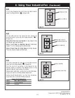
Страница 19: ...m Speed At Medium Speed Two Fan Speed Lights will illuminate Press Three Times for High Speed At High Speed Three Fan Speed Lights will illuminate WALL CONTROL FAN AIRFLOW BUTTON Figure 34 8 3 To set...

Страница 20: ...cessories Downrod Extension Kits 10 Accessories The use of any other control not specifically approved for this fan could result in fire shock and personal injury WARNING Do not use water when cleanin...

Страница 21: ...equipment off and on the user is encouraged to try to correct the interference by one or more of the following measures Reorient or relocate the receiving antenna Increase the separation between the...

Страница 22: ...22 ETL Model No HF1161 12 Repair Parts 18 19 PARTS BAG 17 16 15 14 13 12 11 10 9 8 7 6 5 4 1 4 2 3 5 6 4 6 11 12 13 20 22 21...

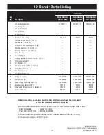
Страница 23: ...55 78 761655 117 760750 106 Consisting of 1 Hanger Bracket 1 2 Hanger Ball 1 3 6 Downrod 1 Parts Bag Containing 764433 1 764433 764433 4 Threaded Studs 8 32 x 75 2 5 Knurled Nuts 8 32 2 6 External Too...

Страница 24: ...Fan 1 Attach Blades to Fan before operating noisy 2 Screws securing Fan Blades to Motor Hub 2 Check to make sure the Screws which attach the Blades are loose to the Motor are tight 3 Loose Screws in...

Страница 25: ...inance Brands Ceiling Fan Product component or Luminance Brands Ceiling Fan Product accessory caused by normal wear and tear rather than due to defects in materials or workmanship Loss or damage resul...

Страница 26: ...You should record this data above and keep it in a safe place for future use Questions problems missing parts Before returning to the store Call Customer Service 1 800 777 4440 www luminancebrands com...

Страница 27: ...o de pieza F40BP75810001 No de formulario BP7581 1 Revisi n 12032020 No de modelo ETL HF1161 LEA Y GUARDE ESTAS INSTRUCCIONES Ventilador industrial de CC de 60 pulgadas Manual del usuario para lugares...

Страница 28: ...industrial 36 40 6 Ensamblaje final 41 7 Instalaci n del control de pared 42 44 8 C mo utilizar su ventilador industrial 44 45 9 Mantenimiento 46 10 Accesorios 46 11 Instrucciones para el usuario 47 1...

Страница 29: ...e cabeza troncoc nica 8 32 x 1 4 de pulg 4 12 Abrazaderas de seguridad para cables 2 13 Tornillo con ojal 1 14 Llave para tornillos de ajuste 1 1 1 Aseg rese de que ha recibido las siguientes piezas N...

Страница 30: ...un electricista con licencia ADVERTENCIA No basta con poner el interruptor de pared en la posici n de apagado Para evitar una posible descarga el ctrica aseg rese de que la electricidad est desconect...

Страница 31: ...3 Utilizando la llave para tornillos de ajuste suministrada retire los dos tornillos de ajuste de la parte superior del yugo del motor Figura 3 Retenga los tornillos de ajuste para uso futuro Figura 3...

Страница 32: ...L TOOTH LOCKWASHER 8 32 x 1 4 PAN HEAD SCREW Figura 4 3 4 Separe destuerza y desenrede los tres cables del motor de 80 pulgadas y el cable de seguridad y luego encam nelos a trav s del agujero central...

Страница 33: ...ables de color marr n azul y gris que miden 80 pulgadas de longitud Antes de instalar el ventilador mida hacia arriba aproximada mente de 6 a 9 pulgadas por encima de la parte superior del ensamblaje...

Страница 34: ...para soportar ventiladores de 22 7 kg 50 lb o menos y utilice los tornillos de montaje suministrados con la caja de tomacorriente La mayor a de las cajas de tomacorriente que se utilizan com nmente pa...

Страница 35: ...av s de las dos abrazaderas para cables NOTA Deje aproximadamente 3 pulgadas de holgura pero no m s de 5 pulgadas en este cable de seguridad con el fin de disponer de un margen en el caso de un posibl...

Страница 36: ...ci n de apagado Para evitar una posible descarga el ctrica aseg rese de que la electricidad est desconectada en la caja de fusibles principal antes de realizar el cableado Todo el cableado debe cumpli...

Страница 37: ...onecte el cable de conexi n a tierra verde de la esfera de suspensi n y el cable de conexi n a tierra verde del soporte de suspensi n al conductor de conexi n a tierra del suministro puede que esto se...

Страница 38: ...W T O M O T O R U T O M O T O R V G G G G A C I N N A C I N L CABLE NEGRO DE SUMINISTRO CABLE NEGRO DEL RECEPTOR CONECTOR DE CABLES P3 Figura 18 CONECTOR DE CABLES P2 CABLE GRIS DEL MOTOR DEL VENTILA...

Страница 39: ...WIRE TO M O TO R W TO MOTOR U Figura 20 5 8 Conecte firmemente el cable azul del receptor TO MOTOR W al cable azul del motor del ventilador utilizando el conector de cables P2 suministrado con el rece...

Страница 40: ...Secci n 7 p gina 42 para la Instalaci n del control de pared Aseg rese de que que todas las conexiones est n apretadas incluyendo la conexi n a tierra y que no haya ning n cable pelado visible en los...

Страница 41: ...os esp rragos roscados e instalando los dos pomos estriados suministrados Figura 25 Apriete de manera segura los pomos estriados hasta que la cubierta del techo quede bien ajustada contra el techo y l...

Страница 42: ...terruptor de pared existente separ ndolo de cable con CORRIENTE negro de la caja de pared Figura 27 Retire el conector de cables del cable negro del interruptor de pared existente del cable de CARGA n...

Страница 43: ...CON V y al cable de CARGA de la caja de pared Figura 29 Conecte firmemente un conector de cables P2 suministrado con el control de pared al cable verde de conexi n a tierra del control de pared y al...

Страница 44: ...su parte inferior Figura 31 Modo de alimentaci n APAGADO Jale el interruptor de ENCENDIDO y APAGADO hacia fuera del control de pared Modo de alimentaci n ENCENDIDO Presione hacia dentro el interrupto...

Страница 45: ...ura 34 8 3 Para ajustar el sentido de giro del ventilador industrial en el control de pared presione el bot n de circulaci n de aire del ventilador Figura 34 El ventilador debe estar funcionando a cua...

Страница 46: ...el ctrica ADVERTENCIA Vea a su distribuidor local de Luminance Brands visite www luminancebrands com o consulte el Cat logo acerca de estos accesorios Kits de extensi n para varillas descendentes 10 A...

Страница 47: ...de determinar apagando y encendiendo el equipo se recomienda al usuario que intente corregir la interferencia tomando una o m s de las siguientes medidas Reoriente o reubique la antena receptora Aumen...

Страница 48: ...48 No de modelo ETL HF1161 18 19 PARTS BAG 17 16 15 14 13 12 11 10 9 8 7 6 5 4 1 4 2 3 5 6 4 6 11 12 13 20 22 21 12 Piezas de repuesto BOLSA DE PIEZAS...

Страница 49: ...as 7 13 Arandelas planas 7 14 Tornillos de cabeza troncoc nica 8 32 x 1 4 de pulg 4 15 Abrazaderas de seguridad para cables 2 16 Tornillo con ojal 1 17 Llave para tornillos de ajuste 1 18 Cubierta del...

Страница 50: ...de que la alimentaci n el ctrica principal est APAGADA 3 Tornillos de la carcasa del motor flojos 3 Aseg rese de que todos los tornillos de la carcasa del motor est n bien apretados no deber n estar...

Страница 51: ...te del Producto de Ventilador de Techo Luminance Brands o accesorio del Producto de Ventilador de Techo Luminance Brands por causa del desgaste por el uso normal en lugar de por causa de defectos de m...

Страница 52: ...ciones ubicada encima de la carcasa del ventilador El c digo de fecha se puede encontrar en la caja de cart n y encima de la carcasa del ventilador estampado en tinta en una etiqueta blanca Usted debe...

Страница 53: ...e ETL N HF1161 HF1161BQ00 Noir barbecue HF1161MS00 Argent m tallique HF1161SW00 Blanc satin Num ros des mod les 1 800 777 4440 www luminancebrands com Questions probl mes pi ces manquantes Avant de re...

Страница 54: ...re tre remplac s Consultez un lectricien agr en cas de doute 4 Connectez toujours correctement le c ble de r tention inclus avec ce ventilateur comme illustr la section 4 de ce mode d emploi Suivez at...

Страница 55: ...4 12 Attache fil de s curit 2 13 Vis il 1 14 Cl vis de pression 1 1 1 V rifiez que vous avez bien re u toutes les pi ces suivantes REMARQUE En cas de doute relatif une description de pi ce r f rez vo...

Страница 56: ...nde murale et le ventilateur ne doit pas d passer 50 m 160 pi Le d passement de cette longueur pourrait causer une perte de contr le ou un contr le inad quat du ventilateur AVERTISSEMENT Il ne suffit...

Страница 57: ...de blocage fendues et deux rondelles plates fournies Figure 2 Recommencez cette proc dure pour les deux autres ensembles de pales Serrez chacune des vis de fixation des pales de fa on s curiser chaque...

Страница 58: ...re 6 MOTOR COVER 8 EXTERNAL TOOTH LOCKWASHER 8 32 x 1 4 PAN HEAD SCREW Figure 4 3 4 S parez d torsadez et d m lez les trois fils du moteur de 2 m 80 po et le c ble de s curit puis acheminez les traver...

Страница 59: ...dante au moyen de la cl Allen fournie 3 9 Le ventilateur comprend des fils marrons bleus et gris de 2 m 80 po de long Avant d installer le ventilateur mesurez environ de 15 23 cm au dessus de l ensemb...

Страница 60: ...de blessure montez le ventilateur sur le bo tier de prises de courant comportant l indication suivante Acceptable for Fan Support of 22 7 kg 50 lbs or less Acceptable pour support de ventilateur de 22...

Страница 61: ...urit travers la vis il puis nouveau travers les deux serre c ble REMARQUE Laissez environ 3 po 7 5 cm mais pas plus de 5 po 12 5 cm de jeu sur ce c ble de s curit afin de tenir compte du mouvement pos...

Страница 62: ...r mural ne suffit pas Pour viter tout choc lectrique ventuel assurez vous que l alimentation lectrique est coup e au niveau du bo tier des fusibles avant d effectuer le c blage Tout le c blage doit tr...

Страница 63: ...t d alimentation lectrique Connectez le fil de mise la terre vert de la rotule de la tige de suspension et le fil de mise la terre vert du support de suspension au conducteur de mise la terre d alimen...

Страница 64: ...W T O M O T O R U T O M O T O R V G G G G A C I N N A C I N L FIL NOIR D ALIMENTATION FIL NOIR DU RECEPTEUR CAPUCHON DE CONNEXION P3 Figure 18 CAPUCHON DE CONNEXION P2 FIL GRIS DU MOTEUR DE VENTILATE...

Страница 65: ...O R W TO MOTOR U Figure 20 5 8 Connectez de fa on s curis e le fil bleu du r cepteur TO MOTOR W au fil bleu du moteur du ventilateur en utilisant le capuchon de connexion P2 fourni avec le r cepteur F...

Страница 66: ...igure 23 REMARQUE Voir Section 7 page 68 pour l Installation de la commande murale AVERTISSEMENT V rifiez que tous les raccordements sont bien serr s y compris la mise la terre et qu aucun fil d nud n...

Страница 67: ...jons filet s et en installant les deux boutons molet s fournis Figure 25 Serrez autant que possible les boutons molet s jusqu ce que la monture de plafond soit ajust e au ras du plafond et jusqu ce qu...

Страница 68: ...nt du fil noir HOT sous tension du bo te murale Figure 27 D tachez le capuchon de connexion du fil noir de l interrupteur mural existant du fil noir LOAD charge du bo te murale Figure 27 REMARQUE Ne t...

Страница 69: ...e murale Figure 29 Connectez de fa on s curis e un capuchon de connexion P2 fourni avec la commande murale au fil de mise la terre vert de la commande murale et au fil en cuivre nu du bo te muralet ou...

Страница 70: ...rupteur de marche arr t ON OFF de la commande murale Mode sous tension ON Appuyez sur l interrupteur de marche arr t ON OFF de la commande murale 7 Installation de la commande murale suite AVERTISSEME...

Страница 71: ...ON Figure 34 8 3 Pour r gler le sens de circulation de l air du ventilateur industriel sur la commande murale appuyez sur le bouton contr lant le sens de circulation de l air Airflow du ventilateur Fi...

Страница 72: ...ue de choc lectrique AVERTISSEMENT Contactez votre revendeur local de produits Luminance Brands allez sur le site www luminancebrands com ou consultez le catalogue pour ces accessoires Kits d extensio...

Страница 73: ...nt l quipement l utilisateur est pri de mettre fin ces bruits parasites en prenant une ou plusieurs des mesures suivantes R orienter l antenne de r ception ou changer sa position Accro tre la s parati...

Страница 74: ...74 Mod le ETL N HF1161 18 19 PARTS BAG 17 16 15 14 13 12 11 10 9 8 7 6 5 4 1 4 2 3 5 6 4 6 11 12 13 20 22 21 12 Pi ces de rechange SAC DE PI CES...

Страница 75: ...o 4 15 Attache fil de s curit 2 16 Vis il 1 17 Cl vis de pression 1 18 Monture de plafond 1 763246 BQ 763246 MS 763246 SW 19 Carter du moteur 1 762494 BQ 762494 MS 762494 SW 20 Ensemble de brides de f...

Страница 76: ...tation est coup e 3 Vis d tach es dans le bo tier du moteur 3 V rifiez que toutes les vis du bo tier du moteur sont bien serr es mais pas excessivement 3 Le ventilateur tremble de mani re excessive 1...

Страница 77: ...entilateur ou Produit pour un ventilateur de plafond Luminance Brands ou un accessoire d un Ventilateur ou Produit pour un ventilateur de plafond Luminance Brands caus s par l usure normale plut t que...

Страница 78: ...78 Mod le ETL N HF1161 Notes Notas Remarques 78...

Страница 79: ...79 luminancebrands com Veuillez t l phoner au 1 800 777 4440 pour toute assistance compl mentaire Mod le ETL N HF1161 Notes Notas Remarques 79...

Страница 80: ...tier du ventilateur Le code de date figure sur le carton et en haut du bo tier du ventilateur Il est estamp l encre sur une tiquette blanche Il faut enregistrer ces informations et les conserver en l...

Отзывы: