Lucent Technologies Lineage
®
2000 ECS Battery Plant H569-416
Issue 2 August 1996
Engineering, Planning & Ordering 3 - 21
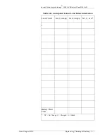
Step K: Calculate the minimum wire size for each battery feeder
in Table 3-B to meet the voltage drop requirements outlined in
paragraphs “Battery Size versus Voltage Drop” and
“Calculating Voltage Drop.”
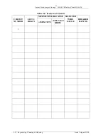
Step L: List the sizes based on voltage drop in Table 3-G.
Step M: Indicate the larger size for each load feeder in the final
column, “Selected Wire Gauge.”
Note
•
Insulation on field wiring conductors should be rated no
less than 75°C. Wire conductor size, determined by the
formula above, should be no less than allowed by
electrical codes for 75°C wire (regardless of insulation
temperature rating used) and the ampacity of the
associated protection device.
•
In order to maintain proper spacings as required by
Underwriters Laboratories when converting load
conductors to the terminal block on the breaker panel, use
only connectors supplied.

