RCI-1502 HRT Tele Boom Manual
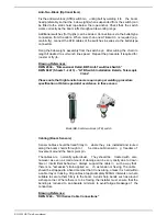
Anti-Two-Block (Optional Item)
Fix the anti-two-block (ATB) switch mo unting bolt by welding it to the boom
head preferably so that the bob weight (when suspended from the switch) can
be fitted to the static hoist rope below the rope anchor. Check that the switch
works correctly as the boom luffs throughout its working range.
Additional switches (for fly-jibs) can be added. Connection is via the bullet-type
connectors from the cab le. When more th an one ATB switch is required (e.g.
main & fly), connect the ATB cables of the switches in series via the bullet-type
connectors.
Hang the bob weight assembly from the switch eye after cutting the chain to
length if desired to suit winch line speed. Repeat the procedure if required for
rooster or fly jib.
Drawing References:
DWG 2934 – “Dimensional Detail, BB5 Anti-Two-Block Switch”
DWG 0667 (Sheets 1-2 of 3) – “ATB Switch Installation Details, Telescopic
Crane”
Please note that high tensile booms require proper welding procedure
specifications. Obtain specialist assistance in these cases.
Model BB-5 anti-two-block (ATB) switch
Cabling (Boom Sensors)
Sensor ca bles should be fixed firmly to where they are installed and routed
along the boom chords through to t
he crane cabin ensurin g freedom of
movement around the boom pivot pin.
The cables are normally quite robust. They should be treated with care,
however, as ev en a small amount of damage can be very costly due to down-
time or intermittent beha viour. Always support the cable in such a way that
there is no "excessive" strain applied, su ch as tension or flexing. The cable
should be strapped to a fixed member that it runs along, unless it is held within
a cable tray or trunking. Clip cables at approximately 600mm intervals or where
suitable to secure them firmly to the boom. Avoid sharp bends such as around
a sharp corner. Where there is to be flexing, the installer must ensure that the
bending is reduced to an absolute minimum to avoid fatigue breakage of the
conductors.
Drawing Reference:
DWG 1224 – “RCI Series Cable Connections”
Содержание RCI-1502 HRT
Страница 2: ......
Страница 4: ......
Страница 6: ......
Страница 8: ......
Страница 14: ......
Страница 22: ......
Страница 44: ......
Страница 52: ......
Страница 56: ......
Страница 58: ......
Страница 59: ...Appendix 8 1 Data Logging on RCI Systems ...
Страница 60: ......
Страница 66: ...Data Logging on RCI Systems Example Lift Cycles ...
Страница 71: ...Appendix 8 2 Drawings ...
Страница 72: ......
Страница 73: ......
Страница 74: ......
Страница 76: ......
Страница 77: ...APPROVED BY TOL 0 0 0 1 2 3 4 55 26 2 0 7 2 8 9 1 1 1 1 0 7 5 6 2 ...
Страница 79: ...APPROVED BY TOL 0 0 0 1 22 3 4 5 6 0 22 2 1 7 8 98 1 7 8 98 7 8 98 7 8 98 1 0 9 8 3 6 8 3 ...
Страница 80: ... APPROVED BY 0 1 2 22 3 3 3 TOL 4 4 23 4 232 22 3 242 4 2 32 2 3516 7 8 7 7 9 2 3 42 4 2 ...
Страница 81: ... APPROVED BY 0 1 2 22 3 3 3 TOL 4 4 23 4 232 22 5 0 42 4 2 3617 8 9 8 8 2 ...
Страница 82: ......
Страница 83: ......
Страница 87: ......
Страница 88: ......
Страница 89: ......
Страница 90: ......
Страница 91: ......
Страница 92: ......
Страница 93: ......
Страница 94: ......
Страница 95: ......
Страница 96: ......
Страница 97: ......
Страница 98: ......
Страница 99: ......
Страница 100: ......
Страница 101: ......
Страница 103: ......
Страница 104: ......
Страница 105: ......
Страница 106: ......
Страница 107: ......
Страница 108: ......
Страница 109: ......


