RCI-1502 HRT Tele Boom Manual
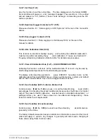
5.2.13. View Calibrated Boom Length Input (F-12)
The calibrated length can be v erified on normal operating mode (operator’s screen).
This function is used to view the calibrated length (in metres or feet) while still in
calibration mode. This is useful when just v erifying accuracy of the bo om length
readout and the calibration has not yet been finalised.
5.2.14. Calibrate Short Boom Length (F-13)
Please see Section 5.4.1. “Calibrating Short Boom Length” for details.
5.2.15. Calibrate Long Boom Length (F-14)
Please see Section 5.4.2. “Calibrating Long Boom Length” for details.
5.2.16. View Uncalibrated Transducer 1 Input (F-15)
Use this function to view the raw coun ts (or raw data) of th e Main Load transducer
(main load sensor). Please also Section 5.1. “Verifying Operation of Se nsors” for
details.
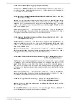
5.2.17. Function Codes (F-16 to F-18) – Not Used
These function codes are used for Load Moment-based systems only.
5.2.18. View Uncalibrated Transducer 2 Input (F-19) – For Twin Winch Cranes
Only
Use this function to view the raw counts (or raw data) of the Aux Load transducer (aux
load sensor). Please also Section 5.1. “Verifying Operation of Sensors” for details.
Please refer to Section 8.3.
“Function Codes ” at the rear of this m anual for the
applicable set of codes. Two sets of codes have been provided in Section 8.3. One is
for Single Winch cranes and the other is for Twin Winch cranes.
5.2.19. Function Codes (F-20 to F-22) – Not Used
These function codes are used for Load Moment-based systems only.
5.2.20. Function Codes (F-23 to F-26) – Not Used
These function codes are used for model RCI-4000IS System only.
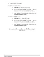
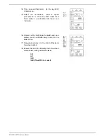
5.2.21. Number of Sensor Samples to Average (F-27)
This function is used to stabilise the di splay in the event that the numbers (readouts
during normal operating mode) are changing erratically. Function code F-27 will show
the number of samples currently being used to average the sensor inputs. This v alue
can be edited by using the Up/Down buttons . Default settin g is “0” and the maximum
selectable value is “25”. Try different settings until the readouts are stable.
Содержание RCI-1502 HRT
Страница 2: ......
Страница 4: ......
Страница 6: ......
Страница 8: ......
Страница 14: ......
Страница 22: ......
Страница 44: ......
Страница 52: ......
Страница 56: ......
Страница 58: ......
Страница 59: ...Appendix 8 1 Data Logging on RCI Systems ...
Страница 60: ......
Страница 66: ...Data Logging on RCI Systems Example Lift Cycles ...
Страница 71: ...Appendix 8 2 Drawings ...
Страница 72: ......
Страница 73: ......
Страница 74: ......
Страница 76: ......
Страница 77: ...APPROVED BY TOL 0 0 0 1 2 3 4 55 26 2 0 7 2 8 9 1 1 1 1 0 7 5 6 2 ...
Страница 79: ...APPROVED BY TOL 0 0 0 1 22 3 4 5 6 0 22 2 1 7 8 98 1 7 8 98 7 8 98 7 8 98 1 0 9 8 3 6 8 3 ...
Страница 80: ... APPROVED BY 0 1 2 22 3 3 3 TOL 4 4 23 4 232 22 3 242 4 2 32 2 3516 7 8 7 7 9 2 3 42 4 2 ...
Страница 81: ... APPROVED BY 0 1 2 22 3 3 3 TOL 4 4 23 4 232 22 5 0 42 4 2 3617 8 9 8 8 2 ...
Страница 82: ......
Страница 83: ......
Страница 87: ......
Страница 88: ......
Страница 89: ......
Страница 90: ......
Страница 91: ......
Страница 92: ......
Страница 93: ......
Страница 94: ......
Страница 95: ......
Страница 96: ......
Страница 97: ......
Страница 98: ......
Страница 99: ......
Страница 100: ......
Страница 101: ......
Страница 103: ......
Страница 104: ......
Страница 105: ......
Страница 106: ......
Страница 107: ......
Страница 108: ......
Страница 109: ......


