


2.
R
emove liner assembl
y
.
(
See
M
aintenance
Section
)
3
.
R
emove gun tube assembl
y
.
(
See
M
aintenance
Section
)
4.
R
emove wire drive assembl
y
.
(
See
M
aintenance
Section
)
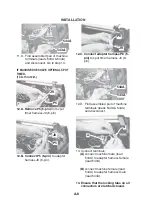
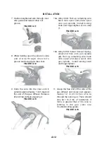
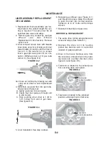
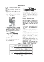
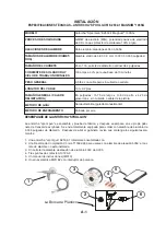
5. Disconnect trigger. Use ad
j
ustable
p
liers to
remove cable strain relie
f
f
rom right handle hal
f
.
(
See
f
igure D.1
3)
FIGURE D.13
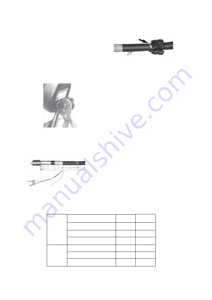
6. Pull damaged cable out o
f
the right handle hal
f
.
The cable connector will
f
it through the strain relie
f
o
p
ening.
M
ark the new cable at a
p
oint 4.750 to
4.81
3
inches
f
rom the end o
f
the cable connector.
(
See
f
igure D.14
)
FIGURE D.14
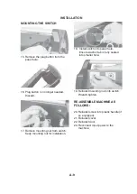
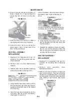
7. Place the strain relie
f
onto the new cable at the
mark as shown in
f
igure D.15.
MAINTENANCE
D-5
FIGURE D.15
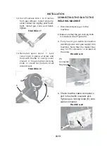
8. Install the new gun cable. Pass the cable connec-
tor through the o
p
ening in the right handle, seat
the strain relie
f
in
p
lace, and then check to insure
the cable is not kinked between strain relie
f
and
connector.
R
eassemble gun b
y
reversing ste
p
s 2
through 5.
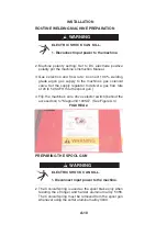
CORRECTING WIRE SHAVING ISSUES
1. I
f
the inlet o
f
the liner assembl
y
is shaving the alu-
minum wire
(
the wire is usuall
y
p
eeled o
ff
in curled
chi
p
s
)
during
f
eeding, the wire
f
eed centerlines o
f
the wire drive and the liner itsel
f
ma
y
be mis-
aligned.
• This misalignment ma
y
occur whenever the gun
tube, wire drive, or welding cable assemblies are
re
p
laced.
• A limited amount o
f
ad
j
ustment is available at the
gun tube mounting to
p
ossibl
y
eliminate the shav-
ing
p
roblem.
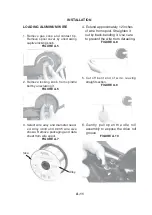
2. Visuall
y
check i
f
wire is centered in the liner
ʼ
s inlet
o
p
ening. Feed wire through the s
p
ool gun and note
which side the shaving seems to occur.
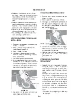
3
.
R
emove le
f
t side o
f
handle. See Figure D.10
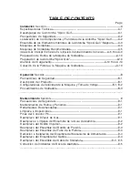
G
un
Tube
R
e
p
lacement. Slightl
y
loosen gun tube
ʼ
s nut
as shown.
4. Slide the gun tube in the mounting
p
late
ʼ
s hole to
realign the wire and then retighten the nut as
shown.
R
eassemble the gun.
5.
R
e
p
eat ste
p
s 2 thru 4 until shaving is eliminated. A
light accumulation o
f
f
ine dust is also
p
ermissible
a
f
ter
f
eeding 1/4 o
f
a s
p
ool during welding use.
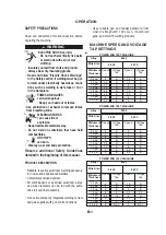
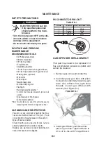
Consumable
parts
Periodic
replacement
parts
Contact tip, 0.030 wire (S19726-2)
Contact tip, 0.035 wire (S19726-3)
Gas diffuser (S19728)
Gas cone assembly (M16294)
Gun tube assembly (S19703-1)
Drive roll assembly (S26236-2)
Liner assembly (S26612)
KP2039-2B1
KP2039-3B1
KP2040-1
KP1938-1
KP2631-1
KP2529-2
KP2632-1
10-pack
10-pack
1-piece
1-piece
1-piece
1-piece
1-piece
TABLE D.2
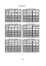
M
ark
f
or strain relie
f
Содержание K2532-1
Страница 3: ......
Страница 4: ......
Страница 22: ...NOTES MAGNUM 100SG...
Страница 36: ...MAGNUM 100SG NOTES...
Страница 41: ......
Страница 58: ...NOTAS MAGNUM 100SG...
Страница 72: ...MAGNUM 100SG NOTES NOTAS...
Страница 75: ......
Страница 76: ......
Страница 94: ...NOTES MAGNUM 100SG...
Страница 108: ...MAGNUM 100SG NOTES MAGNUM 100SG NOTES...
Страница 109: ...NOTES NOTAS MAGNUM 100SG...
Страница 115: ...NOTES NOTAS MAGNUM 100SG...


