


MAINTENANCE
D-4
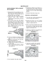
4. Obtain a new re
p
lacement gun tube
(
i
f
need-
ed
)
.
R
emove locking nut
f
rom old gun tube and
install onto new gun tube.
N
ut should be
f
ull
y
threaded
f
inger-tight against the insulating
tube.
5. Slide gun tube
ʼ
s external threads through gun
tube mounting
p
late and screw the gun tube b
y
hand into the cable connector until the nut
p
ulls
the mounting
p
late snug against the connector.
6. Tighten the nut and mounting
p
late to the con-
nector with Tor
q
ue Wrench 10 to 12
f
t.-lbs.
7.
R
eassemble gun. Be care
f
ul not to
p
inch an
y
leads between gun handle halves.
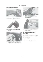
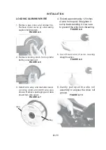
WIRE DRIVE ASSEMBLY REMOVAL AND
INSTALLATION
1. There are no serviceable or maintainable
p
arts
inside o
f
the wire drive.
2.
R
emove liner assembl
y
(
See
M
aintenance
Section
f
igures D.2 and D.
3)
.
3
.
R
emove le
f
t side o
f
handle.
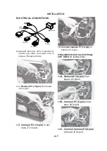
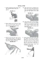
4. Disconnect black and red leads
f
rom drive
motor. Use care to
p
revent damage to motor
ʼ
s
f
ast-on electrical tabs.
5. Slide wire drive out o
f
right handle hal
f
.
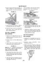
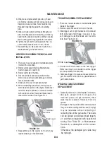
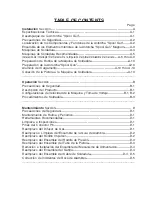
6. When reinstalling wire drive, note the
p
ro
p
er
motor lead connection in the
f
igure.
R
econnect
red motor lead to
p
ositive
(
+
)
terminal, marked
with red dot at arrow.
R
econnect black lead to
other motor terminal.
(
See
f
igure D.11
)
FIGURE D.11
7.
R
eassemble gun. Be care
f
ul not to
p
inch an
y
leads between gun handle halves.
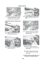
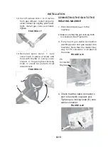
TRIGGER ASSEMBLY REPLACEMENT
1. There are no serviceable or maintainable
p
arts
inside o
f
the trigger.
2.
R
emove s
p
ool cover and le
f
t side o
f
handle.
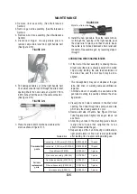
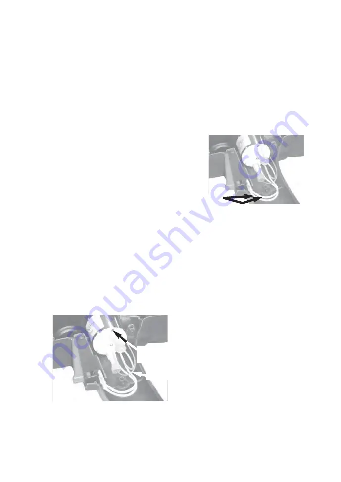
3
. Slide trigger out o
f
right handle hal
f
. Disconnect
both white leads
f
rom trigger. Use care to
p
re-
vent damage to electrical leads and the termi-
nals.
(
See Figure D.12
)
FIGURE D.12
4. Connect both white leads to the new trigger.
Either lead ma
y
be connected to either trigger
p
in
(
non-
p
olari
z
ed connections
)
.
5. Slide new trigger into
p
lace and reassemble the
gun. Be care
f
ul not to
p
inch an
y
leads between
gun handle halves.
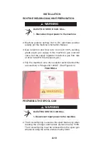
WELDING CABLE ASSEMBLY
REPLACEMENT
1.
G
enerall
y
, there are no serviceable or maintain-
able
p
arts, exce
p
t
f
or both o-rings on the
machine
ʼ
s
p
ower and gas connector; these
seals ma
y
be re
p
laced. However, there are
o
p
tions:
• Damage to the
f
our #22 AW
G
control leads at
the gun cable
ʼ
s welding machine end
(
P6
p
lug
)
ma
y
be re
p
airable without
removing or
re
p
lacing the entire gun cable. The leads
can be s
p
liced and soldered back togeth-
er, and then reinsulated with heat-shrink
tubing. See Table D.1 in
M
aintenance
Section
f
or a descri
p
tion o
f
the connec-
tions.
• Otherwise, the damaged gun cable ma
y
be re
p
laced.
White Leads
“
+
”
Terminal
R
ed Dot
Black Lead
Содержание K2532-1
Страница 3: ......
Страница 4: ......
Страница 22: ...NOTES MAGNUM 100SG...
Страница 36: ...MAGNUM 100SG NOTES...
Страница 41: ......
Страница 58: ...NOTAS MAGNUM 100SG...
Страница 72: ...MAGNUM 100SG NOTES NOTAS...
Страница 75: ......
Страница 76: ......
Страница 94: ...NOTES MAGNUM 100SG...
Страница 108: ...MAGNUM 100SG NOTES MAGNUM 100SG NOTES...
Страница 109: ...NOTES NOTAS MAGNUM 100SG...
Страница 115: ...NOTES NOTAS MAGNUM 100SG...


