background image

SFA-5000  •  SFA-10000  DeviceNet

EXAMPLE

We install the following draw-wire encoder: 

SFA-5000-FD-8192-M12

.

The physical values are:
Stroke per turn of the drum = 200 mm (7.874”)
Physical resolution per turn = 13 bits = 8,192 cpr
Max. number of physical revolutions = 4,096 revolutions
Total physical resolution = 25 bits = 33 554 432 information
Physical linear resolution = 0.024 mm = 24 µm
Max. number of turns of the drum = 25
Max. measuring length = 5,000 mm (196.85”)
Number of information = 204,800
Let's suppose that we need a tenth of a millimetre linear resolution in the
specific installation.

Enable the scaling function: 

4 Scaling function control

 attribute = 1

Custom resolution per turn = 

5 Measuring units/rev

 = 2,000 cpr

Linear resolution = 0.1 mm = 100 µm

Linear resolution = 

Stroke per turn

 = 

200

 = 0.1 mm

5 Measuring units/rev

2,000

The custom number of revolutions can be as the physical number of revolutions:

Custom number of encoder revolutions =

6 Total measuring range

 = 4,096

5 Measuring units/rev

6 Total measuring range

 = 8 192 000

NOTE

Please note that if you set a preset along the path, when the encoder moves
back and cross the zero, the value immediately after 0 will be 8 192 000 - 1, i.e.
8 191 999.

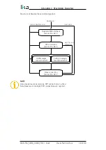
...

8,191,997

8,191,998

8,191,999

0

1

2

...

EXAMPLE

Using the values in the previous example let's suppose that the travel in the
application   is   2   m   long.   As   the   stroke   per   turn   is   200   mm   you   need   10
revolutions to cover the travel length.

6 Total measuring range

 = 

5 Measuring units/rev

 * custom number

of revolutions = 2,000 * 10 = 20,000

In fact:

Custom number of encoder revolutions =

6 Total measuring range

 = 10

5 Measuring units/rev

MAN SFA_5000_10000_FD E 1.0.odt Quick reference (using RSNetWorx)42 of 88

Содержание SFA-10000-FD

Страница 1: ...ons DeviceNet interface Group 2 only server devices Suitable for the following models SFA 5000 FD SFA 10000 FD General Contents Preliminary information 10 Mounting instructions 14 Electrical connections 18 Quick reference using RSNetWorx 27 DeviceNet interface 48 Setup 80 Default parameters table 84 Lika Electronic Tel 39 0445 806600 info lika biz www lika biz Smart encoders actuators ...

Страница 2: ...ion herein is subject to change without notice and should not be construed as a commitment by Lika Electronic s r l Lika Electronic s r l reserves the right to make all modifications at any moments and without forewarning This manual is periodically reviewed and revised As required we suggest checking if a new or updated edition of this document is available at Lika Electronic s r l s website Lika...

Страница 3: ...ection 22 4 5 Connection of the shield 22 4 6 Setting the baud rate DIP A 23 4 7 Setting the node address DIP B 24 4 8 Setting the RT bus termination 25 4 9 Diagnostic LEDs 26 5 Quick reference using RSNetWorx 27 5 1 Import EDS file 27 5 2 Adding a node to the project 29 5 3 Encoder parameters configuration 29 5 4 Saving the parameters with RSNetWorx 33 5 5 Using the scanner module 34 5 6 Paramete...

Страница 4: ... value 53 Already in requested mode state 53 Object state conflict 53 Attribute not settable 53 Device state conflict 53 Not enough data 53 Attribute not supported 53 Too much data 53 Object does not exist 54 Invalid parameter 54 6 4 3 Explicit Messages Connection 55 6 4 4 Message data transfer 56 6 5 Object dictionary 57 6 5 1 Class 01h Identity Object 58 01 01 01 Vendor ID 58 01 01 02 Device typ...

Страница 5: ...med connection path 64 05 Inst 11 Production inhibit time 65 6 5 4 Class 23h Position Sensor Object 66 23 01 03 Position value 66 23 01 0B Device type 68 23 01 0C Code sequence 68 23 01 0E Scaling function control 68 23 01 10 Resolution per revolution 69 23 01 11 Total measuring range 70 23 01 13 Preset value 73 23 01 14 Delta for COS 75 23 01 18 Velocity value 75 23 01 19 Velocity format 75 23 01...

Страница 6: ...value in the Object dictionary 80 7 1 3 Setting 23 01 13 Preset value 81 7 1 4 Saving the parameters 81 7 1 5 Closing the Master Slave connection 82 7 2 Setting the Cyclic mode without velocity 82 7 2 1 P2P Master Slave connection 82 7 2 2 Setting 05 Inst 09 Expected packet rate for Cyclic mode milliseconds 82 8 Default parameters table 84 ...

Страница 7: ...on 69 23 01 11 Total measuring range 70 23 01 13 Preset value 73 23 01 14 Delta for COS 75 23 01 18 Velocity value 75 23 01 19 Velocity format 75 23 01 2A Hardware counts per revolution 75 23 01 2B Hardware number of turns 76 23 01 2C Alarms 76 23 01 2D Supported alarms 76 23 01 2E Alarm flags 77 23 01 33 Offset 77 23 01 65 Dip switch 77 23 01 66 Data Tx in Poll mode 77 23 01 67 Data Tx in COS Cyc...

Страница 8: ...solution revolution 44 Position 37 Position sensor type 38 Preset value 43 R Resource unavailable 53 S Scaling function control 39 Service not supported 53 Supported alarms 45 T Too much data 53 Total measuring range 41 V Velocity format 46 Velocity value 46 ...

Страница 9: ...ant to highlight the parts of the text where information of great significance for the user can be found user must pay the greatest attention to them Instructions must be followed strictly in order to guarantee the safety of the user and a correct use of the device Failure to heed a warning or comply with instructions could lead to personal injury and or damage to the unit or other equipment This ...

Страница 10: ...of the moving equipment causes the wire to reel and unreel and thus the linear movement to be converted into a rotary motion detected by the encoder which is coupled to the drum The stroke per turn is always 200 mm 7 874 the maximum number of turns is 25 for SFA 5000 and 50 for SFA 10000 To make it easier to read and understand the text this guide is divided into two main sections In the first sec...

Страница 11: ...ection on page 18 in compliance with the 2014 30 EU norm on electromagnetic compatibility following precautions must be taken before handling and installing discharge electrical charge from your body and tools which may come in touch with the device power supply must be stabilized without noise install EMC filters on device power supply if needed always use shielded cables twisted pair cables when...

Страница 12: ... by manufacturer we suggest installing the unit providing protection means against waste especially swarf as turnings chips or filings should this not be possible please make sure that adequate cleaning measures are in place in order to prevent the wire from jamming to avoid failures never exceed the maximum measuring length and prevent the wire from tangling up never release the wire freely alway...

Страница 13: ...al number when reaching Lika Electronic for purchasing spare parts or needing assistance For any information on the technical characteristics of the product refer to the technical catalogue Warning encoders having order code ending with Sxxx may have mechanical and electrical characteristics different from standard and be supplied with additional documentation for special connections Technical inf...

Страница 14: ...lectrical connection and maintenance operations must be carried out by qualified personnel only with power supply disconnected Mechanical components must be in stop 3 1 Overall dimensions Values are expressed in mm MAN SFA_5000_10000_FD E 1 0 odt Mounting instructions 14 of 88 ...

Страница 15: ... using the provided M6 nuts 2 WARNING We suggest installing the unit providing protection means against waste especially swarf as turnings chips or filings should this not be possible please make sure that adequate cleaning measures are in place in order to prevent the wire from jamming To avoid irreparable failures never exceed the maximum measuring length and prevent the wire from tangling up MA...

Страница 16: ... 874 the maximum number of turns is 25 for SFA 5000 and 50 for SFA 10000 EXAMPLE 1 SFA 5000 FD 8192 PG using the physical resolution 23 01 0E Scaling function control 00 Stroke per turn of the drum 200 mm 7 874 23 01 2A Hardware counts per revolution physical resolution per turn 13 bits 8 192 cpr 23 01 2B Hardware number of turns number of physical revolutions 12 bits 4 096 revolutions Total physi...

Страница 17: ...0 information example Custom number of encoder revolutions 23 01 11 Total measuring range 4 096 23 01 10 Resolution per revolution Linear resolution 0 1 mm 100 µm Max number of turns of the drum 50 Max measuring length 10 000 mm 393 7 Number of information 100 000 3 4 Maintenance The measuring system does not need any particular maintenance anyway it has to be handled with the utmost care as any d...

Страница 18: ... be caused to internal components The terminal connectors for connecting the power supply and the BUS IN and BUS OUT cables PG cable version as well as the DIP switches meant to set the node ID and the baud rate and activate the termination resistance PG cable version and M12 connector version are located inside the encoder connection cap Thus you must remove the connection cap to access any of th...

Страница 19: ...he connection cap at the end of the operation Take care in re connecting the internal connector Tighten the screws 1 using a tightening torque of approx 2 5 Nm WARNING You are required to check that the encoder body and the connection cap are at the same potential before replacing the connection cap MAN SFA_5000_10000_FD E 1 0 odt Electrical connections 19 of 88 ...

Страница 20: ...each cable gland You can use either cable for power supply We recommend DeviceNet certificated cables to be used Core diameter should not exceed Ø 1 5 mm 0 06 inches Terminal connector Description 0 Vdc Supply voltage 10Vdc 30Vdc Supply voltage G CAN GND 1 L CAN Low H CAN High PG CAN Shield 2 1 CAN GND is the 0V reference of CAN signals it is not connected to 0Vdc supply voltage 2 Connect the cabl...

Страница 21: ...a complete list of the available cordsets and patchcords please refer to the product datasheet Accessories list M12 5 pin connector A coding frontal side male BUS IN female BUS OUT M12 Description Case CAN Shield 1 1 2 10Vdc 30Vdc power supply voltage 3 0Vdc power supply voltage 4 CAN High 5 CAN Low 1 CAN Shield is also connected to pin 1 to allow the connection of the shield even if the plug conn...

Страница 22: ...nectors are used connect the cable shield properly as recommended by the manufacturer Anyway make sure that ground is not affected by noise It is recommended to provide the ground connection as close as possible to the device We suggest using the ground point provided in the cap see the Figures use one TCEI M3 x 6 cylindrical head screw with two tooth lock washers 4 5 Connection of the shield Dise...

Страница 23: ...that ON 1 OFF 0 bit 1 LSB 2 MSB 3 4 20 21 OFF OFF Table of the available baud rate values Binary value Baud rate 00 125 Kbit s 01 250 Kbit s 10 500 Kbit s default NOTE Bits 3 and 4 must be always set to OFF EXAMPLE Set the baud rate to 250 Kbit s 01 binary value see the table above bit 1 2 3 4 ON OFF OFF OFF Set the baud rate to 500 Kbit s 10 binary value see the table above bit 1 2 3 4 OFF ON OFF...

Страница 24: ...The default address is 1 Set the node address in binary value ON 1 OFF 0 bit 1 LSB 2 3 4 5 6 MSB 7 not used 8 not used 20 21 22 23 24 25 EXAMPLE Set the node address 25 2510 0001 10012 binary value bit 1 2 3 4 5 6 7 8 20 21 22 23 24 25 ON OFF OFF ON ON OFF OFF OFF Set the node address 55 5510 0011 01112 binary value bit 1 2 3 4 5 6 7 8 20 21 22 23 24 25 ON ON ON OFF ON ON OFF OFF MAN SFA_5000_1000...

Страница 25: ...f the encoder is at the ends of the transmission line i e it is either the first or the last device in the transmission line Use RT Switch to activate or deactivate the bus termination RT Description 1 2 ON Activated if the encoder is the first or the last device in the transmission line 1 2 OFF Deactivated if the encoder is not the first or the last device in the transmission line MAN SFA_5000_10...

Страница 26: ...ot on line Red ON Encoder communication failure Flashing red Connection time out Green ON Device on line and connected Flashing green Device on line but not connected Flashing green red Communication error MS LED Description OFF No power supply Red ON Unrecoverable fault see 01 01 05 Status attribute on page 58 Flashing red Recoverable fault may need replacing see 01 01 05 Status attribute on page...

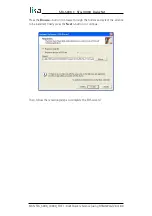
Страница 27: ...AW WIRE ABSOLUTE EDS file must be installed in the Master device In this section the installation and configuration of the device using Rockwell Automation s RSNetWorx program are described On the menu bar of the RSNetWorx window select the Tools menu and then press the EDS Wizard command In the EDS Wizard window select Register an EDS file s option and then press Next button MAN SFA_5000_10000_FD...

Страница 28: ...utton to browse through the folders and select the eds file to be installed finally press the Next button to continue Then follow the remaining steps to complete the EDS wizard MAN SFA_5000_10000_FD E 1 0 odt Quick reference using RSNetWorx 28 of 88 ...

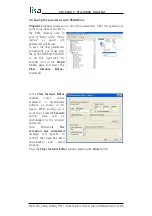
Страница 29: ...onic SNC Generic Device drag the required module SFA xxxxx FD to the Graph tabbed page on the right 5 3 Encoder parameters configuration Double click the encoder icon in the Graph tabbed page and open the Properties window Or right click the encoder icon and press the Properties command in the menu MAN SFA_5000_10000_FD E 1 0 odt Quick reference using RSNetWorx 29 of 88 ...

Страница 30: ...SFA 5000 SFA 10000 DeviceNet Open the General tabbed page of the Properties window and set the node address in the Address box MAN SFA_5000_10000_FD E 1 0 odt Quick reference using RSNetWorx 30 of 88 ...

Страница 31: ...tention to 16 Data Tx in POLL mode 17 Data Tx in COS Cyclic mode and 20 Auto save parameters attributes 16 Data Tx in POLL mode and 17 Data Tx in COS Cyclic mode attributes must be set in accordance with the scanner module settings see the 5 5 Using the scanner module section on page 34 MAN SFA_5000_10000_FD E 1 0 odt Quick reference using RSNetWorx 31 of 88 ...

Страница 32: ... scanner module section on page 34 Click the Upload button to upload and read the current configuration Click the Download button to send the new parameters to the encoder NOTE If 20 Auto save parameters YES the new parameters values are saved automatically otherwise if 20 Auto save parameters NO you must start manually the save parameters procedure see the following 5 4 Saving the parameters with...

Страница 33: ...t click the encoder icon in the Graph tabbed page and select the Class Instance Editor command In the Class Instance Editor window enter values expressed in hexadecimal notation as shown in the Figure When setting up is carried out press the Execute button data will be downloaded to the encoder and saved Soon afterwards The execution was completed message will appear to confirm that data has been ...

Страница 34: ...ndow if requested upload the configuration Open the Scanlist tabbed page Select Lika device in the Available Devices pane on the left and move it to the Scanlist pane on the right pressing the button Now double click the item in the Scanlist pane to open the Edit I O parameters window MAN SFA_5000_10000_FD E 1 0 odt Quick reference using RSNetWorx 34 of 88 ...

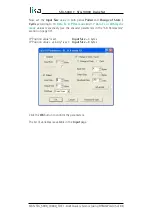
Страница 35: ...yclic mode values respectively see the encoder parameters in the 5 6 Parameters section on page 37 If Position value is set Input Size 4 bytes If Position value velocity is set Input Size 8 bytes Click the OK button to confirm the parameters The list of variables is available in the Input page MAN SFA_5000_10000_FD E 1 0 odt Quick reference using RSNetWorx 35 of 88 ...

Страница 36: ...alue velocity 17 Data Tx in COS Cyclic mode Position value Polled messages Variables Bytes Input 1 1 1 2 Position value 1 2 3 4 1 3 5 6 Velocity value 1 4 7 8 COS messages Variables Bytes Input 1 5 1 2 Position value 1 6 3 4 MAN SFA_5000_10000_FD E 1 0 odt Quick reference using RSNetWorx 36 of 88 ...

Страница 37: ...ing calculation Linear resolution Stroke per turn of the drum Singleturn resolution cpr If you want to know the linear position value you will need to multiply the transmitted position value by the linear resolution Linear position value transmitted position linear resolution NOTE Please note that the encoder s linear resolution can be read also in the order code next to the rotary resolution Refe...

Страница 38: ...be as follows Linear position value 1 569 0 05 78 45 mm 78 450 µm 2 Position sensor type Type of device 2 Multiturn absolute rotary encoder Default 2 min 2 max 2 3 Counting direction 3 Counting direction attribute sets whether the position value output by the encoder increases count up information when you rewind the wire 0 or when you pull the wire out 1 default 0 rewinding the wire the position ...

Страница 39: ... change the scaling values see the 5 Measuring units rev and 6 Total measuring range attributes then you are required to set a new preset value see the 7 Preset value attribute and finally save the new parameters see the 5 4 Saving the parameters with RSNetWorx section on page 33 5 Measuring units rev WARNING This attribute is active only if the 4 Scaling function control attribute is set to 1 oth...

Страница 40: ...lutions 33 554 432 6 Total measuring range 93 206 755 360 5 Measuring units rev As you can see the encoder is required to carry out more than 93 000 revolutions this cannot be as the hardware number of revolutions is as stated 4 096 When this happens the encoder falls into an error signalling the faulty condition through the diagnostic LEDs see on page 26 WARNING When you enable the scaling functi...

Страница 41: ...set to a power of 2 The set Number of revolutions results from the following calculation Number of revolutions 6 Total measuring range 5 Measuring units rev Setting the Number of revolutions to a value which is a power of 2 is meant to avoid problems when using the device in endless operations requiring the physical zero to be overstepped If you set the Number of revolutions which is not a power o...

Страница 42: ...near resolution Stroke per turn 200 0 1 mm 5 Measuring units rev 2 000 The custom number of revolutions can be as the physical number of revolutions Custom number of encoder revolutions 6 Total measuring range 4 096 5 Measuring units rev 6 Total measuring range 8 192 000 NOTE Please note that if you set a preset along the path when the encoder moves back and cross the zero the value immediately af...

Страница 43: ...hysical position will get the value set next to this item and all the previous and following positions will get a value according to it This function can be useful for instance when the zero position of the encoder and the zero position of the axis need to match The preset value will be set for the position of the encoder i e the position of the wire in the moment when the preset value is transmit...

Страница 44: ... value read position 1001 7 Preset value 50 12 Offset value 1000 51 And so on NOTE If the scaling function is disabled see the 4 Scaling function control attribute the 7 Preset value must be less than or equal to the Total hardware resolution 1 8 Physical resolution revolution 9 Physical number of revolutions 1 If the scaling function is enabled see the 4 Scaling function control attribute the 7 P...

Страница 45: ... The Total hardware resolution results from 8 Physical resolution revolution 9 Physical number of revolutions If you want to set a custom number of revolutions see the 5 Measuring units rev and 6 Total measuring range attributes on page 39 ff Default 4 096 10 Alarms An alarm is set when a bit indicating a fault is set to true high See the 11 Supported alarms values Default 0 min 0 max 32 767 11 Su...

Страница 46: ...pressed in number of steps per second or in revolutions per minute see the 14 Velocity format attribute 14 Velocity format This attribute sets the engineering units for the velocity value 13 Velocity value steps s 0 number of steps per second default value rpm 1 revolutions per minute Default 0 min 0 max 1 15 Dip switch This attribute shows the status of the dip switches Dip switches are located i...

Страница 47: ...n the Change Of State COS mode connection is enabled this parameter sets the minimum gap between two I O messages Values too low could cause the Bus network to saturate Default 5 min 0 max 262 143 20 Auto save parameters NO 0 New parameters are not saved on EPROM automatically To save new values Class Instance Editor must be used default value see the 5 4 Saving the parameters with RSNetWorx secti...

Страница 48: ...he communication messages CAN ID CAN Data bytes 11 bit from 3 to 8 bytes Lika DeviceNet draw wire encoders support two kinds of communication messages I O messages I 0 messages are high priority messages Their meaning is explained in the Message ID Slave device uses these messages to send process data For further information see the 6 3 I O Messages Msg group 1 section on page 50 Explicit messages...

Страница 49: ...us or multiple P2P connections are rejected MAN SFA_5000_10000_FD E 1 0 odt DeviceNet interface 49 of 88 P2P connection see section 6 4 3 Config messages see section 6 4 4 I O Messages see section 6 3 power up communications error wait for new connection Close connection see section 6 4 3 Duplicate MAC ID check see section 6 4 1 reset node ...

Страница 50: ... If the expected packet rate of polled mode is null see 05 Inst 09 Expected packet rate attribute communication is always active and time out status is never triggered otherwise if the Slave does not receive any message from the Master within the time set in the 05 Inst 09 Expected packet rate attribute then the communication is closed time out status Cyclic the Slave sends an I O message cyclical...

Страница 51: ...data transfer send receive data configuration see the 6 4 4 Message data transfer section on page 56 CAN ID table of explicit message bit 10 9 8 7 6 5 4 3 2 1 0 1 0 MAC ID Msg ID MAC ID device address Msg ID 0002 Master s I O Bit Strobe Command Msg 0012 Master s I O Multicast Poll Command Msg 0102 Master s I O COS Cyclic Acknowledge Msg 0112 Slave s Explicit Unconnected Response Msg 1002 Master s ...

Страница 52: ... number 6 serial number High byte R R bit 0 duplicate MAC ID check request This message is sent by a device to all nodes in the network 1 duplicate MAC ID check response This message is sent back to the sender by the node in the network having the same MAC ID Port number 0 device that allows only one P2P connection When serial number node ID and vendor ID are not single univocal in the network an ...

Страница 53: ...defined in an Application Object Specification 08h Service not supported The requested service was not implemented or was not defined for this Object Class Instance 09h Invalid attribute value Invalid attribute data detected 0Bh Already in requested mode state The object is already in the mode state being requested by the service 0Ch Object state conflict The object cannot perform the requested se...

Страница 54: ...uest was invalid This code is used when a parameter does not meet the requirements of this specification and or the requirements defined in an Application Object Specification For any further information on general error codes refer to the publication The CIP Networks Library Volume I Common Industrial Protocol CIP MAN SFA_5000_10000_FD E 1 0 odt DeviceNet interface 54 of 88 ...

Страница 55: ...C ID 1 R R 1 Service Code 4Bh 2 General error code Close connection request Byte bit7 bit6 bit5 bit4 bit3 bit2 bit1 bit0 0 F 0 0 Master MAC ID 1 R R 0 Service Code 4Ch 2 Class ID 03h 3 Instance ID 01h 4 Release choice Allocation Choice Close connection response Byte bit7 bit6 bit5 bit4 bit3 bit2 bit1 bit0 0 F 0 0 Master MAC ID 1 R R 1 Service Code 4Ch 2 General error code Allocation choice bit 7 R...

Страница 56: ... Class ID 3 Instance ID 4 Attribute ID 5 7 Data byte Data transfer response Byte bit7 bit6 bit5 bit4 bit3 bit2 bit1 bit0 0 F 0 0 Master MAC ID 1 R R 1 Service Code 2 7 Data byte Service code Class ID Instance ID and Attribute ID are meant to set the type and content of data bytes They must be specified according to the Object dictionary see the 6 5 Object dictionary section on page 57 MAN SFA_5000...

Страница 57: ...t 1 byte UINT unsigned integer 16 bit 2 bytes UDINT unsigned double integer 32 bit 4 bytes WORD 16 bit specify 2 bytes Access type ro read only access rw read and write access NOTE All data bytes are sent from least significant byte LSB to most significant byte MSB EXAMPLE UDINT 4 data bytes Byte bit7 bit6 bit5 bit4 bit3 bit2 bit1 bit0 0 F 0 0 Master MAC ID 1 R R 1 Service Code 2 Data byte Low byt...

Страница 58: ...INT ro Hardware and software revisions the Identity Object represents LSByte MSByte Major revision Minor revision 01 01 05 Status WORD ro This attribute represents the current status of the device Its value changes as the state of the device changes Bit definitions are as follows Bit s Called Definition 0 Owned TRUE indicates the device or an object within the device has an owner Within the Master...

Страница 59: ... not cause the device to go into one of the faulted states 9 Minor unrecoverable fault TRUE indicates that the device detected a problem with itself which is thought to be unrecoverable The problem does not cause the device to go into one of the faulted states 10 Major recoverable fault TRUE indicates that the device detected a problem with itself which caused the device to go into the Major Recov...

Страница 60: ...SFA 5000 SFA 10000 DeviceNet 01 01 07 Product name SHORT_STRING ro Default 05 4C 49 4B 41 20h LIKA MAN SFA_5000_10000_FD E 1 0 odt DeviceNet interface 60 of 88 ...

Страница 61: ...he node address DIP B section on page 24 03 01 02 Baud rate USINT ro This attribute shows the set baud rate Binary value Baud rate 00 125 Kbit s 01 250 Kbit s 10 500 Kbit s default To set the baud rate see the 4 6 Setting the baud rate DIP A section on page 23 03 01 03 Bus off interrupt BOOL ro This attribute sets how the device has to act after a bus off event 00 when a bus off event occurs devic...

Страница 62: ... Master Slave Connections is active 2nd byte Master s MAC ID contains the MAC ID of the device that has allocated the Predefined Master Slave Connection The FFh value means that the Predefined Master Slave Connection has not been allocated no communication active MAN SFA_5000_10000_FD E 1 0 odt DeviceNet interface 62 of 88 ...

Страница 63: ... means that the connection has been configured correctly 05 Inst 02 Instance type USINT ro 00h Explicit messaging 01h I O messaging 05 Inst 03 TransportClass_trigger BYTE ro It defines whether this is a producing only consuming only or both producing and consuming connection 05 Inst 04 Produced connection ID UINT ro This is the value that will be specified in the CAN Identifier Field when this Con...

Страница 64: ...ically closes the connection after the Inactivity Watchdog Timer gap has expired 05 Inst 0D Produced connection path length UINT ro This attribute specifies the number of bytes the 05 Inst 0E Produced connection path attribute consists of 05 Inst 0E Produced connection path EPATH ro This attribute is fitted with a byte stream which defines the Application Object s whose data is to be produced by t...

Страница 65: ...no inhibit time NOTE To save the parameters execute the Save parameters function see 7 1 4 Saving the parameters in the 7 1 Read and set parameters section on page 81 When the power is turned off parameters not saved are lost MAN SFA_5000_10000_FD E 1 0 odt DeviceNet interface 65 of 88 ...

Страница 66: ...tion detected by the position sensor The output value is scaled according to the scaling attributes see the 23 01 0E Scaling function control attribute Reading the position 23 01 03 Position value see also on page 80 Master Encoder CAN ID 5 Data byte 404 ID 3 Ms SC Cl Ins At 00 0E 23 01 03 Encoder Master CAN ID 6 Data byte 403 ID 3 Ms SC position 00 8E Low High WARNING Please note that the positio...

Страница 67: ...solution of the measuring device is 8 192 cpr 0 024 mm see the order code in the product datasheet As stated the linear resolution results from the following calculation Linear resolution Stroke per turn of the drum Singleturn resolution cpr Linear resolution 200 0 024 mm 24 µm 8 192 Let s say that the transmitted position value is 123 Thus the linear position value will be as follows Linear posit...

Страница 68: ...the new parameters execute the Save parameters function see 7 1 4 Saving the parameters in the 7 1 Read and set parameters section on page 81 23 01 0E Scaling function control BOOL rw If this attribute is disabled OFF 00 the device uses the physical resolution values see the 23 01 2A Hardware counts per revolution and 23 01 2B Hardware number of turns attributes if it is enabled ON 01 it uses the ...

Страница 69: ...e the position information This attribute sets a custom number of distinguishable steps per revolution custom singleturn resolution To avoid counting errors check that 23 01 2A Hardware counts per revolution integer value 23 01 10 Resolution per revolution You are allowed to set whatever integer value less than or equal to the maximum number of physical steps per revolution see the hardware counts...

Страница 70: ... physical values In the case of inconsistent values the system will warn about the wrong parametrization and fault condition by means of the dedicated attributes and visually by means of the diagnostic LEDs WARNING Every time you change the scaled values see the 23 01 10 Resolution per revolution and 23 01 11 Total measuring range attributes then you are required to set a new preset value see the ...

Страница 71: ...e next to the 23 01 11 Total measuring range attribute please always check also the 23 01 10 Resolution per revolution attribute value and be sure that the resulting number of revolutions complies with the Hardware number of revolutions of the device 4 096 revolutions Let s suppose that the encoder is programmed as follows 23 01 10 Resolution per revolution 8 192 cpr 23 01 11 Total measuring range...

Страница 72: ...reset along the path when the encoder moves back and cross the zero the value immediately after 0 will be 8 192 000 1 i e 8 191 999 8 191 997 8 191 998 8 191 999 0 1 2 EXAMPLE Using the values in the previous example let s suppose that the travel in the application is 2 m long As the stroke per turn is 200 mm you need 10 revolutions to cover the travel length 23 01 11 Total measuring range 23 01 1...

Страница 73: ...n of the encoder i e a position in the travel of the wire The chosen physical position will get the value set next to this item and all the previous and following positions will get a value according to it This function can be useful for instance when the zero position of the encoder and the zero position of the axis need to match The preset value will be set for the position of the encoder i e th...

Страница 74: ...fset 0 When you set the 23 01 13 Preset value and then execute the preset setting the system saves the current encoder position in the 23 01 33 Offset attribute It follows that the transmitted value and the 23 01 13 Preset value are the same as read position 23 01 33 Offset 0 in other words the value set next to the 23 01 13 Preset value attribute is paired with the current position of the encoder...

Страница 75: ...he Change Of State COS mode connection is enabled this parameter sets the minimum interval between two I O messages Values too low could cause the Bus network to saturate Default 05h 23 01 18 Velocity value UDINT ro This attribute represents the current speed detected by the position sensor and calculated every 100 ms The speed can be expressed in number of steps per second or in revolutions per m...

Страница 76: ...w the number of physical revolutions provided by the hardware number of physical revolutions The Total hardware resolution results from 23 01 2A Hardware counts per revolution 23 01 2B Hardware number of turns If you want to set a custom number of revolutions see the 23 01 10 Resolution per revolution and 23 01 11 Total measuring range attributes on page 69 ff 23 01 2C Alarms WORD ro An alarm is s...

Страница 77: ...f the related attributes 23 01 13 Preset value and 23 01 33 Offset please refer to page 73 23 01 65 Dip switch UINT ro This attribute shows the status of the dip switches Dip switches are located in the connection cap and used to set the baud rate and the MAC ID see the sections 4 6 Setting the baud rate DIP A and 4 7 Setting the node address DIP B bits 0 5 MAC ID bits 6 and 7 not used bits 8 and ...

Страница 78: ... 33 1 Yes when new parameters are set the encoder waits 5 seconds and then saves automatically all new values on EPROM but only if the received value has been changed NOTE To save new parameters execute the Save parameters function see 7 1 4 Saving the parameters in the 7 1 Read and set parameters section on page 81 When the power is turned off or in case of Reset node and Restore node commands pa...

Страница 79: ... Instance 01h Explicit Message 2B 01 01 Acknowledge timer UINT rw After a Master request the Slave waits for the set acknowledgement time before sending back a reply Default 10h 16 ms 2B 01 02 Retry Limit USINT rw Number of Ack Timeouts after which the application informs the Master that a RetryLimit_Reached event occurred 2B 01 03 Connection Instance of COS UINT rw Connection Instance which conta...

Страница 80: ...SC Service Code Cl Class Ins Instance AC Allocation Choice At Attribute Err Error code 7 1 Read and set parameters 7 1 1 P2P Master Slave connection without I 0 msg Master Encoder request CAN ID 6 Data byte 406 ID 3 Ms SC Cl Ins AC Ms 00 4B 03 01 01 00 Encoder Master response CAN ID 3 Data byte 403 ID 3 Ms SC Err 00 CB 00 7 1 2 Reading the position 23 01 03 Position value in the Object dictionary ...

Страница 81: ...ster Encoder 2nd message CAN ID 4 Data byte 404 ID 3 Ms FC preset 80 81 Hi Encoder Master 2nd message received CAN ID 3 Data byte 403 ID 3 Ms SC Err 80 C1 00 Encoder Master parameter value accepted CAN ID 3 Data byte 403 ID 3 Ms SC Err 00 90 00 7 1 4 Saving the parameters Master Encoder CAN ID 5 Data byte 404 ID 3 Ms SC Cl Ins At 00 16 23 01 01 Encoder Master CAN ID 3 Data byte 403 ID 3 Ms SC Err ...

Страница 82: ... P2P Master Slave connection Master Encoder request CAN ID 6 Data byte 406 ID 3 Ms SC Cl Ins AC Ms 00 4B 03 01 61 00 Encoder Master response CAN ID 3 Data byte 403 ID 3 Ms SC Err 00 CB 00 7 2 2 Setting 05 Inst 09 Expected packet rate for Cyclic mode milliseconds Master Encoder CAN ID 7 Data byte 404 ID 3 Ms SC Cl Ins At Ctime 00 10 05 04 09 Low Hi Encoder Master CAN ID 3 Data byte 403 ID 3 Ms SC E...

Страница 83: ...at the interval set in the 05 Inst 09 Expected packet rate attribute until the connection will be closed or the 05 Inst 09 Expected packet rate attribute will be modified Encoder Master CAN ID 4 Data byte 340 ID position Low Hi MAN SFA_5000_10000_FD E 1 0 odt Setup 83 of 88 ...

Страница 84: ... out 4 Scaling function control 0 DISABLED 5 Measuring units rev 8192 6 Total measuring range 33 554 432 7 Preset value 0 14 Velocity format 0 STEPS S 16 Data Tx in POLL mode 0 POSITION VALUE 17 Data Tx in COS Cyclic mode 0 POSITION VALUE 19 Delta for COS 5 20 Auto save parameters 0 NO MAN SFA_5000_10000_FD E 1 0 odt Default parameters table 84 of 88 ...

Страница 85: ...This page intentionally left blank ...

Страница 86: ...This page intentionally left blank ...

Страница 87: ...This page intentionally left blank ...

Страница 88: ...elease Release date Description HW SW EDS file version 1 0 19 04 2018 1st issue 1 0 1 002 V1 Lika Electronic Via S Lorenzo 25 36010 Carrè VI Italy Tel 39 0445 806600 Fax 39 0445 806699 info lika biz www lika biz ...

Отзывы: