IPECS Release 5
Hardware Description & Installation
Issue 5.0
96
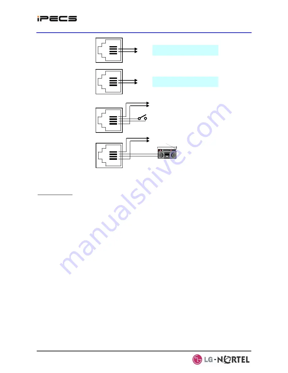
To PSTN Tip/Ring terminations
1
2
3
4
CO
Tip
Ring
1
2
3
4
SLT
Tip
Ring
To SLT Tip/Ring terminations
1
2
3
4
Relay2
Alarm
Relay 2 Contact
Alarm
1
2
3
4
Relay1
BGM
Relay 1 Contact
BGM source
To PSTN Tip/Ring terminations
1
2
3
4
CO
Tip
Ring
To PSTN Tip/Ring terminations
1
2
3
4
1
2
3
4
CO
Tip
Ring
Tip
Ring
1
2
3
4
SLT
Tip
Ring
To SLT Tip/Ring terminations
1
2
3
4
1
2
3
4
SLT
Tip
Ring
Tip
Ring
To SLT Tip/Ring terminations
1
2
3
4
Relay2
Alarm
Relay 2 Contact
Alarm
1
2
3
4
1
2
3
4
Relay2
Alarm
Relay 2 Contact
Alarm
1
2
3
4
Relay1
BGM
Relay 1 Contact
BGM source
1
2
3
4
1
2
3
4
Relay1
BGM
Relay 1 Contact
BGM source
Figure 4.5.16-3 RSGM Connections
AC/DC Adapter
Assure the AC/DC Adapter is plugged into a live AC outlet and the Module Power jack.
Содержание IPECS
Страница 1: ...Hardware Description Installation Manual ...
Страница 50: ...IPECS Release 5 Hardware Description Installation Issue 5 0 40 Figure 2 3 4 4 Wall Mount Installation ...
Страница 68: ...IPECS Release 5 Hardware Description Installation Issue 5 0 58 Figure 4 3 5 3 1U RMB Rack mount Installation ...
Страница 72: ...IPECS Release 5 Hardware Description Installation Issue 5 0 62 Figure 4 4 3 Monitoring cable Installation ...
Страница 108: ...IPECS Release 5 Hardware Description Installation Issue 5 0 98 Figure 4 5 17 1 POE8 Installation ...
Страница 111: ...IPECS Release 5 Hardware Description Installation Issue 5 0 101 Figure 4 5 18 1 Cascading connections of WTIM4 8 ...
Страница 121: ...Hardware Description Installation Manual ...


