IPECS Release 5
Hardware Description & Installation
Issue 5.0
33
Speed
Trans/Pgm
Dnd
Call Back
Navigation buttons
In addition, the LIP-7016, 7024D and 7024LD include 3 Soft buttons. The function of these buttons
is interactive and shown in the lower line of the LCD.
The LIP-7008D includes a 2-line, 48-character (24 characters per line) Liquid Crystal Display
(LCD). The LCD provides an alphanumeric display to assist the user in operation of features. In
the idle mode, the display will show the station name or number on the top line and the time and
date on the 2
nd
line. The LCD is employed to support features such as Dial-By-Name (Directory
Dial) using the Volume control to scroll through name displays to find a telephone number in the
directory.
The LIP-7000 series IP phone circuitry includes Digital Signal Processing to implement packet
voice encoding and decoding, and echo cancellation as well as tone generation and speakerphone
operation. The Volume control, which consists of a single volume up/down rocker button, adjusts
the level of the handset receiver, speaker as well as the headset receiver, when used.
The LIP-7000 series IP phone may be powered locally with the AC/DC Adapter, reference section
2.2.3, or powered over the LAN with the POE8 or other 802.3af compliant Ethernet switch. If both
the AC/DC Adapter and powered LAN port are connected to the LIP-7000 terminal, the Adapter will
provide the required power.
Using the appropriate Wall Mount Kit, the LIP-7000 terminal can be mounted on a wall. Two
handset hooks, which are used to keep the handset in-place, are molded as part of the Wall Mount
bracket. One hook must be removed from the bracket and inserted in the slot just below the hook-
switch to hold the handset when wall mounted. Note; the matching Console is not wall-mountable.
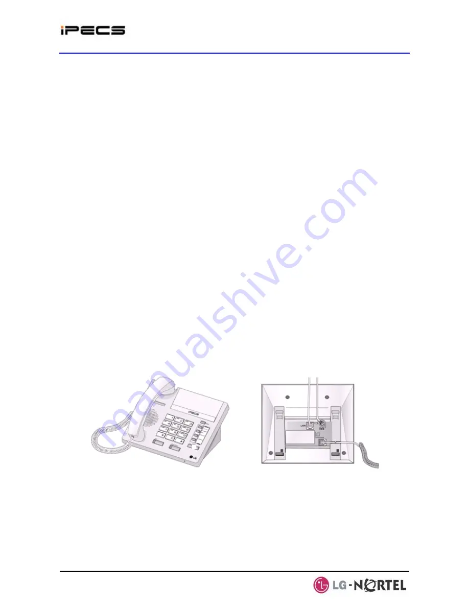
Figure 2.2.2-1 LIP-7004N
Содержание IPECS
Страница 1: ...Hardware Description Installation Manual ...
Страница 50: ...IPECS Release 5 Hardware Description Installation Issue 5 0 40 Figure 2 3 4 4 Wall Mount Installation ...
Страница 68: ...IPECS Release 5 Hardware Description Installation Issue 5 0 58 Figure 4 3 5 3 1U RMB Rack mount Installation ...
Страница 72: ...IPECS Release 5 Hardware Description Installation Issue 5 0 62 Figure 4 4 3 Monitoring cable Installation ...
Страница 108: ...IPECS Release 5 Hardware Description Installation Issue 5 0 98 Figure 4 5 17 1 POE8 Installation ...
Страница 111: ...IPECS Release 5 Hardware Description Installation Issue 5 0 101 Figure 4 5 18 1 Cascading connections of WTIM4 8 ...
Страница 121: ...Hardware Description Installation Manual ...


