IPECS Release 5
Hardware Description & Installation
Issue 5.0
56
¾
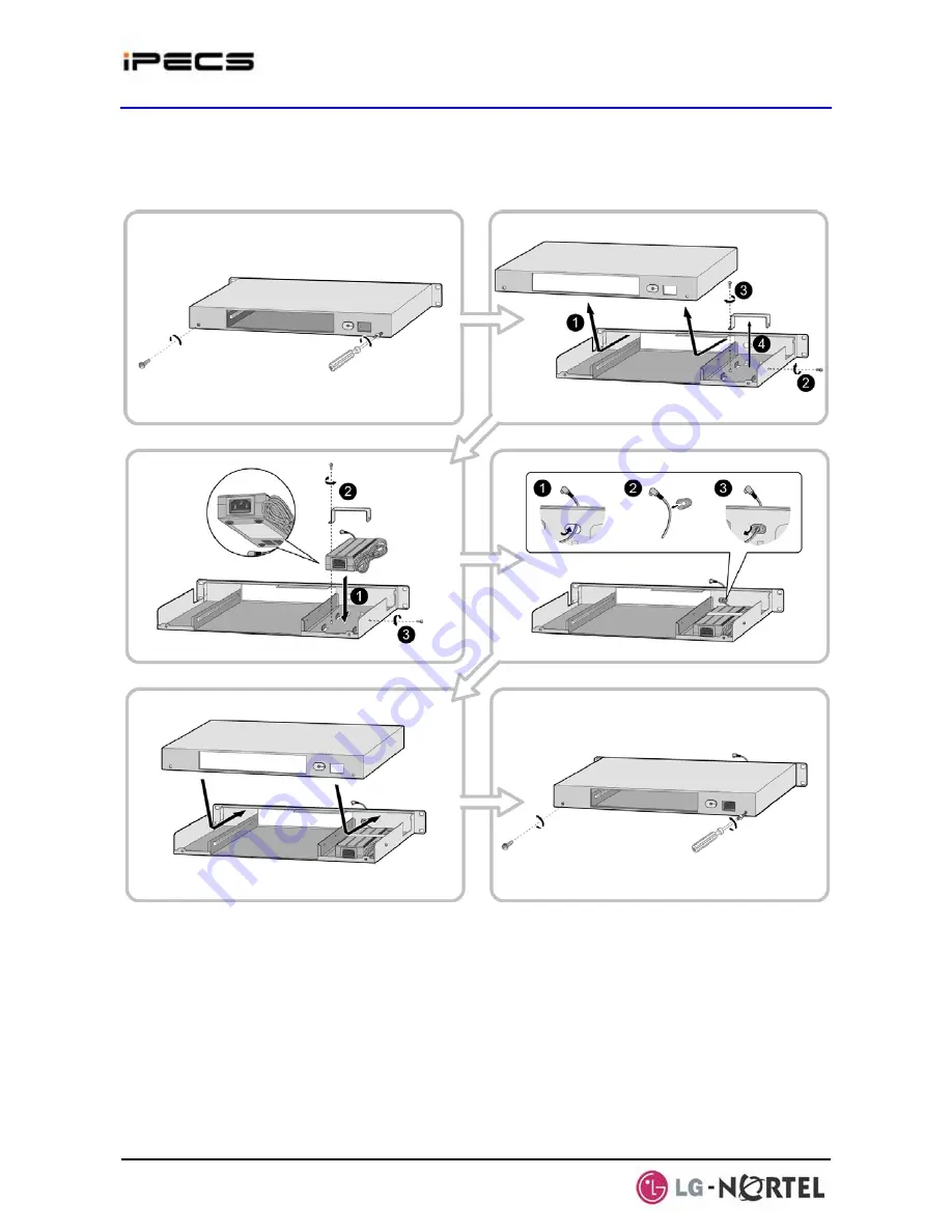
Insert the rubber grommet over the DC adapter cable and insert the grommet in the
hole in the front of the housing.
¾
Replace the upper housing and fasten the two (2) screws.
Figure 4.3.5-1 1U RMB Adapter Installation
2. Install the gateway Module into the 1U-RMB and connect the adapter plug. Refer to Figure
4.3.5-2.
¾
Slide the Module into the 1U-RMB.
¾
Place the Ferrite core over the DC cable and close the core over the cable. For the
RSGM, the DC cable must exit the rear of the 1U-RMB. For all other modules, the DC
cable must exit the front of the 1U-RMB.
¾
Connect the adapter DC plug to the gateway Module.
Содержание IPECS
Страница 1: ...Hardware Description Installation Manual ...
Страница 50: ...IPECS Release 5 Hardware Description Installation Issue 5 0 40 Figure 2 3 4 4 Wall Mount Installation ...
Страница 68: ...IPECS Release 5 Hardware Description Installation Issue 5 0 58 Figure 4 3 5 3 1U RMB Rack mount Installation ...
Страница 72: ...IPECS Release 5 Hardware Description Installation Issue 5 0 62 Figure 4 4 3 Monitoring cable Installation ...
Страница 108: ...IPECS Release 5 Hardware Description Installation Issue 5 0 98 Figure 4 5 17 1 POE8 Installation ...
Страница 111: ...IPECS Release 5 Hardware Description Installation Issue 5 0 101 Figure 4 5 18 1 Cascading connections of WTIM4 8 ...
Страница 121: ...Hardware Description Installation Manual ...


