IPECS Release 5
Hardware Description & Installation
Issue 5.0
65
4.5.1.4
Module
Grounding
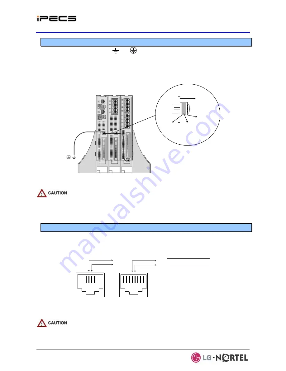
As shown in Figure 4.5.1.4-1, a “ ” or “ “ screw is located on the rear panel of each Module.
For proper operation and code compliance, the grounding screw
MUST
be connected to a
known protective earth ground using a #12 AWG or larger UL-1015 type copper wire. The wire
should be located between the toothed lock washer and the plain washer. Note that when using
the cabinet, a separate ground connection to the individual Modules is not required.
Toothed lock
washer
Plan washer
rear panel
Wire position
Plain washer
Figure 4.5.1.4-1 Module Grounding
When a module is installed in a Desk Mount Holder (DHLD) Wall Mount Holder
(WHLD) or 1U-Rack Mount Bracket (1U-RMB), the protective earth ground must be
connected to the earth ground terminal in rear of the module using #12 AWG or
larger UL-1015 type copper wire.
4.5.1.5
Telephony
Connections
In general, PSTN and SLT (telephony) connections are available on the rear of each Module,
while LAN, power and RS-232 connections are on the front of each Module. Telephony
connections via RJ-11 or RJ-45 type jacks are wired as in Figure 4.5.1.5-1. All telephone wiring
should use standard two (2)-pair twisted 24 or 26 AWG wiring.
1 2 3 4
TIP
RING
RJ-11 Connector
1 2 3 4
TIP
RING
RJ-11 Connector
1 2 3 4 5 6 7 8
RJ-45 Connector
TIP
RING
1 2 3 4 5 6 7 8
RJ-45 Connector
TIP
RING
To PSTN Tip/Ring terminations
or SLT Tip/Ring terminations
Figure 4.5.1.5-1 Telephony (RJ-11 or RJ-45) Connector Pin Assignment
To reduce the risk of fire, use only 26 AWG or larger UL List or CSA Certified
Telecommunication Line Cord.
Содержание IPECS
Страница 1: ...Hardware Description Installation Manual ...
Страница 50: ...IPECS Release 5 Hardware Description Installation Issue 5 0 40 Figure 2 3 4 4 Wall Mount Installation ...
Страница 68: ...IPECS Release 5 Hardware Description Installation Issue 5 0 58 Figure 4 3 5 3 1U RMB Rack mount Installation ...
Страница 72: ...IPECS Release 5 Hardware Description Installation Issue 5 0 62 Figure 4 4 3 Monitoring cable Installation ...
Страница 108: ...IPECS Release 5 Hardware Description Installation Issue 5 0 98 Figure 4 5 17 1 POE8 Installation ...
Страница 111: ...IPECS Release 5 Hardware Description Installation Issue 5 0 101 Figure 4 5 18 1 Cascading connections of WTIM4 8 ...
Страница 121: ...Hardware Description Installation Manual ...


