Diagnostic aids
3-11
7526
Go Back
Previous
Next
Press
Stop
(
) to return to the Scanner Tests Menu.
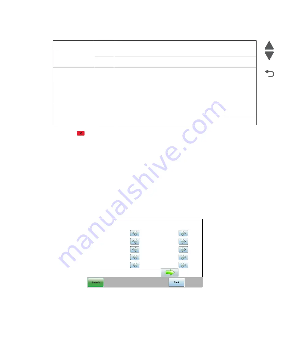
Alignment Menu
Note:
If you need to perform alignment or registration, see
“Printhead alignment” on page 4-9
The following information is meant to explain the uses for the menu items.
Alignment is part of the process of adjusting the printhead and the color planes to the black plane and to each
other. Before you start, perform the black alignment (Registration). See
“Printhead alignment” on page 4-9
. If
you are replacing a new printhead, see
“Printhead removal, installation, and adjustment” on page 4-147
.
To perform alignment:
1.
Touch
ALIGNMENT MENU
from Diag Menu.
2.
Select one of the colors; cyan, yellow, or magenta.
3.
Touch the arrows next to the settings, and then set the values to zero.
4.
Continue for all colors; cyan, yellow, and magenta.
5.
Touch
Submit
.
Note:
It is important to zero out all settings to make the adjustment easier.
6.
Touch
Quick Test
Quick Test printing...
is displayed, and then two pages print.
7.
On the pages, make sure all the Current Values are set to zero. If not, go back to step 2 and repeat.
Paper FB Long
0
Legal paper is not present on the flatbed, or the scanner is not closed
1
Legal paper is present on the flatbed, is covering the third length sensor,
and the scanner cover is closed
Paper ADF Long
0
Paper not present in the ADF, or positioned over the ADF bin sensor
1
Paper present in the ADF, and positioned over the ADF bin sensor.
Paper ADF Width 1
0
Paper present in the ADF, and the paper edge guide is moved to the
Executive position
1
Paper is not present in the ADF, or the paper edge guide is not positioned in
the Executive position
Paper ADF Width 2
0
Paper present in the ADF, and the paper edge guide is moved to the
Executive position
1
Paper is not present in the ADF, or the paper edge guise is not position in
the Executive position
Sensor Test descriptions (under Scanner Tests)
Sensor
State
Description
Cyan
Left Margin
Right Margin
Skew
Bow
Top Margin
Quick Test
0
0
0
0
0
Содержание X734DE
Страница 10: ...x Service Manual 7526 Go Back Previous Next...
Страница 15: ...Notices and safety information xv 7526 Go Back Previous Next...
Страница 16: ...xvi Service Manual 7526 Go Back Previous Next...
Страница 22: ...xxii Service Manual 7526 Go Back Previous Next...
Страница 254: ...3 58 Service Manual 7526 Go Back Previous Next Printer base...
Страница 266: ...3 70 Service Manual 7526 Go Back Previous Next...
Страница 277: ...Repair information 4 11 7526 Go Back Previous Next d Touch Quick Test A page similar to this one prints...
Страница 293: ...Repair information 4 27 7526 Go Back Previous Next 4 Remove the five larger screws B and the two smaller screws C...
Страница 300: ...4 34 Service Manual 7526 Go Back Previous Next 4 Remove the five larger screws B and the two smaller screws C...
Страница 316: ...4 50 Service Manual 7526 Go Back Previous Next 7 Remove the six screws G 8 Remove the screw H in front...
Страница 324: ...4 58 Service Manual 7526 Go Back Previous Next 6 Grasp the auger shaft C and remove it C...
Страница 328: ...4 62 Service Manual 7526 Go Back Previous Next 5 Remove the two screws C 6 Remove the cartridge cooling fan C...
Страница 359: ...Repair information 4 93 7526 Go Back Previous Next 14 Remove the two screws O on the inside O P...
Страница 360: ...4 94 Service Manual 7526 Go Back Previous Next 15 Remove the seven screws R securing the EP drive R R First R R...
Страница 398: ...4 132 Service Manual 7526 Go Back Previous Next 3 Insert the motor into the frame 4 Replace the screws C...
Страница 422: ...4 156 Service Manual 7526 Go Back Previous Next f Touch Quick Test A page similar to this one prints...
Страница 464: ...4 198 Service Manual 7526 Go Back Previous Next 4 Remove the five larger screws B and the two smaller screws C...
Страница 482: ...4 216 Service Manual 7526 Go Back Previous Next 9 Remove the two screws G G 18B1236...
Страница 495: ...Repair information 4 229 7526 Go Back Previous Next 5 Lift the cover from the ADF...
Страница 513: ...Repair information 4 247 7526 Go Back Previous Next 5 Grasp the cover on the lower right and pull up...
Страница 571: ...Connector locations 5 1 7526 Go Back Previous Next 5 Connector locations Locations printer base...
Страница 572: ...5 2 Service Manual 7526 Go Back Previous Next Connectors System board...
Страница 582: ...5 12 Service Manual 7526 Go Back Previous Next...
Страница 588: ...6 6 Service Manual 7526 Go Back Previous Next...
Страница 592: ...7 4 Service Manual 7526 Go Back Previous Next Assembly 2 Front 5 2 3 4 7 9 11 A B D 8 10 12 E 13 C G F F 1 6...
Страница 594: ...7 6 Service Manual 7526 Go Back Previous Next Assembly 3 Right 1 2 3 4 5 6...
Страница 596: ...7 8 Service Manual 7526 Go Back Previous Next Assembly 4 Rear...
Страница 602: ...7 14 Service Manual 7526 Go Back Previous Next Assembly 8 Covers scanner 6 8 9 10 5 7 11 14 1 2 13 3 4 12...
Страница 604: ...7 16 Service Manual 7526 Go Back Previous Next Assembly 9 Automatic document feeder ADF...
Страница 606: ...7 18 Service Manual 7526 Go Back Previous Next Assembly 10 Flatbed scanner...
Страница 612: ...7 24 Service Manual 7526 Go Back Previous Next Assembly 14 Options and features...
Страница 614: ...7 26 Service Manual 7526 Go Back Previous Next...
Страница 622: ...I 8 Service Manual 7526 Go Back Previous Next...
Страница 626: ...I 12 Service Manual 7526 Go Back Previous Next...


