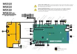
WIRING DIAGRAM
JP_PRE1 JINDEX1 JACM1 JMPF1 JT_PRE1 J24
JDUPP1
JPS1
JLIFT1
JRESET
JNRW1
JHDD1
JISP1
JOPT1
JFAX1
JURFW1
JUAREG1
JT3
J2
JSWISH1
J47
J1
J43
JMCLR1
JBINS1
JTHM1
JEXIT1
JFAN1
JT
AG1
J20
J10
J44
JLSU1
J6
JFBM1
JFAN2
JCIS1
JHOME1
JPLEN1
JADF1
JUICC
JCTLS1
JAR
W2
JAR
W1
JMTR1
JTDS
JBT2 JBT1
JAUD1
JBT3
JCAR
T1
J4
JSWISS1
J56
FUSER ASSEMBLY
MAIN MOTOR
TONER CARTRIDGE MOTOR
LIFT PLATE MOTOR
PCN1
PCN5
Sw1
PCN6
PCN7
PCN4
PCN3
PCN2
POWER SUPPLY
LASER
SCANNING
UNIT
FRONT
COVER
SENSOR
FA
N
REVERSE
SOLENOID
WIRELESS
OPTION
USB MALE PI
USB TYPE A
WIRELESS OPTION
ETHERNET
SPEAKER
J3
J2
OPERATOR PANEL
OP PANEL USB
TOUCH SCREEN
UICC
TONER LEVEL SENSOR
CARTRIDGE SMARTCHIP CONTACTS
IMAGING UNIT SMARTCHIP CONTACTS
INPUT SENSOR
DUPLEX SENSOR
PAPER HANDLING OPTIONS
AUTOCONNECT
TRANSFER ROLL SPRING
JT_PRE1
JMPF1
JACM1
JINDEX1
JP_PRE1
INDEX SENSOR
TRAILING EDGE SENSOR
MPF SENSOR
TRAY PRESENT SENSOR
MEDIA PRESENT SENSOR
MPF SOLENOID
NARROW MEDIA /
BIN FULL SENSOR
IMAGING UNIT CONTACTS
( OPC & CHARGE )
TONER DENSITY SENSOR
Содержание M3150
Страница 12: ...Part name index 393 4514 6xx Table of contents 12 ...
Страница 20: ...4514 6xx 20 ...
Страница 38: ...4514 6xx 38 ...
Страница 172: ...4514 6xx 172 ...
Страница 233: ...c Insert the cable into the hole B d Route the cable using the new path 4514 6xx Parts removal 233 ...
Страница 246: ...3 Remove two screws A and then remove the cooling fan mount A 4514 6xx Parts removal 246 ...
Страница 256: ...5 Remove the four screws B and then remove the right front mount B 4514 6xx Parts removal 256 ...
Страница 258: ...Cartridge plunger removal 1 Open the front door 2 Tilt the cartridge plunger 4514 6xx Parts removal 258 ...
Страница 260: ...b Set the spring over the plunger 4514 6xx Parts removal 260 ...
Страница 262: ...Bezel removal MS610dn 1 Open the front door 2 Push the latches A and then remove the bezel A 4514 6xx Parts removal 262 ...
Страница 277: ...3 Squeeze the latches B to release the left and right links B 4514 6xx Parts removal 277 ...
Страница 300: ...3 Place the printer on its rear side 4 Release the sensor flag A 4514 6xx Parts removal 300 ...
Страница 301: ...5 Remove the screw B 6 Remove the sensor flag bracket C 4514 6xx Parts removal 301 ...
Страница 306: ...8 Remove the three screws A A 9 Disconnect the cable from the pick lift motor gearbox 4514 6xx Parts removal 306 ...
Страница 323: ...3 Swing the right cover backward to remove 4 Remove the screw D 4514 6xx Parts removal 323 ...
Страница 333: ...4514 6xx 333 ...
Страница 335: ...Assembly 1 Covers 4514 6xx Parts catalog 335 ...
Страница 338: ...4514 6xx Parts catalog 338 ...
Страница 339: ...Assembly 2 Electronics 1 1 2 3 4 5 7 9 10 11 6 8 12 4514 6xx Parts catalog 339 ...
Страница 342: ...4514 6xx Parts catalog 342 ...
Страница 343: ...Assembly 3 Electronics 2 4 3 2 1 5 6 8 9 7 4514 6xx Parts catalog 343 ...
Страница 345: ...4514 6xx Parts catalog 345 ...
Страница 346: ...Assembly 4 Frame 10 11 12 13 14 9 1 5 6 7 8 4 4 2 3 4514 6xx Parts catalog 346 ...
Страница 349: ...Assembly 5 Option trays 3 4 5 6 1 2 4514 6xx Parts catalog 349 ...
Страница 354: ...4514 6xx Parts catalog 354 ...
Страница 356: ...4514 6xx Parts catalog 356 ...
Страница 364: ...4514 6xx 364 ...
Страница 376: ...4514 6xx 376 ...
Страница 386: ...4514 6xx Index 386 ...
Страница 392: ...4514 6xx Part number index 392 ...
Страница 398: ...4514 6xx Part name index 398 ...


