Electrophotographic process (EP process)
Printhead
The printhead scans the photo conductor drum surface with a laser beam. It consists of the following
components:
•
Laser diode (LD) card assembly
•
Oscillator
•
Start of scan card assembly
When a laser beam is scanned across the photoconductor drum surface from one end to the other while turning
on and off the beam, one line of latent image is created. If the scanning by the laser beam is repeated while
rotating the drum, a two-dimensional image is created. The resolution in the scanning direction (from right to
left) is determined by the rotational speed of the printhead motor, depending on how quickly the laser is
adjusted. The resolution in the process direction (from top to bottom) is determined by the rotational speed of
the printhead motor. The higher the scanning speed becomes, the sooner the scanning of the next row can be
started.
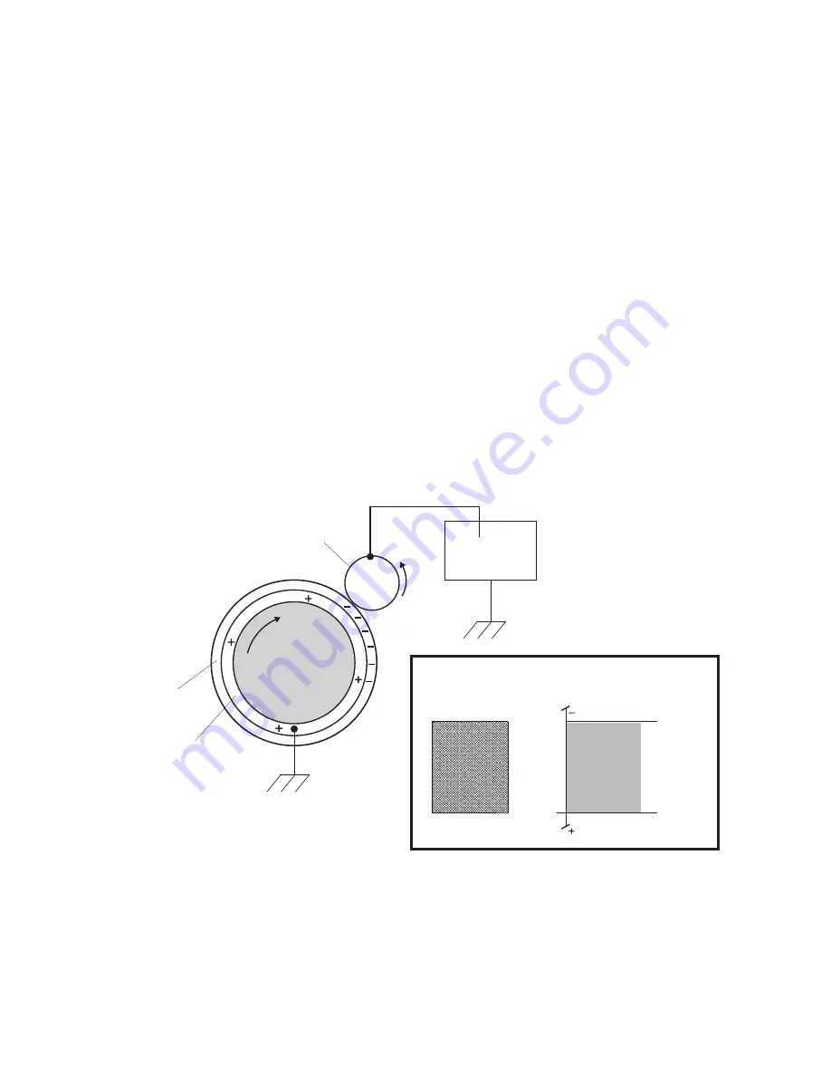
Step 1: Charge
During the charge step, voltage is sent from the HVPS to the charge roll beside the photoconductor. The charge
roll applies a uniform negative charge over the entire surface of the photoconductor to prepare it for the laser
beam.
HVPS
(-VDC)
(-VDC)
Ground
Conductive Tube
Photoconductive
Surface
0V
-VDC value
DRUM
Drum Surface
Voltage
Drum Surface
Image
Ground
Charge roll
4514-6xx
Theory of operation
372
Содержание M3150
Страница 12: ...Part name index 393 4514 6xx Table of contents 12 ...
Страница 20: ...4514 6xx 20 ...
Страница 38: ...4514 6xx 38 ...
Страница 172: ...4514 6xx 172 ...
Страница 233: ...c Insert the cable into the hole B d Route the cable using the new path 4514 6xx Parts removal 233 ...
Страница 246: ...3 Remove two screws A and then remove the cooling fan mount A 4514 6xx Parts removal 246 ...
Страница 256: ...5 Remove the four screws B and then remove the right front mount B 4514 6xx Parts removal 256 ...
Страница 258: ...Cartridge plunger removal 1 Open the front door 2 Tilt the cartridge plunger 4514 6xx Parts removal 258 ...
Страница 260: ...b Set the spring over the plunger 4514 6xx Parts removal 260 ...
Страница 262: ...Bezel removal MS610dn 1 Open the front door 2 Push the latches A and then remove the bezel A 4514 6xx Parts removal 262 ...
Страница 277: ...3 Squeeze the latches B to release the left and right links B 4514 6xx Parts removal 277 ...
Страница 300: ...3 Place the printer on its rear side 4 Release the sensor flag A 4514 6xx Parts removal 300 ...
Страница 301: ...5 Remove the screw B 6 Remove the sensor flag bracket C 4514 6xx Parts removal 301 ...
Страница 306: ...8 Remove the three screws A A 9 Disconnect the cable from the pick lift motor gearbox 4514 6xx Parts removal 306 ...
Страница 323: ...3 Swing the right cover backward to remove 4 Remove the screw D 4514 6xx Parts removal 323 ...
Страница 333: ...4514 6xx 333 ...
Страница 335: ...Assembly 1 Covers 4514 6xx Parts catalog 335 ...
Страница 338: ...4514 6xx Parts catalog 338 ...
Страница 339: ...Assembly 2 Electronics 1 1 2 3 4 5 7 9 10 11 6 8 12 4514 6xx Parts catalog 339 ...
Страница 342: ...4514 6xx Parts catalog 342 ...
Страница 343: ...Assembly 3 Electronics 2 4 3 2 1 5 6 8 9 7 4514 6xx Parts catalog 343 ...
Страница 345: ...4514 6xx Parts catalog 345 ...
Страница 346: ...Assembly 4 Frame 10 11 12 13 14 9 1 5 6 7 8 4 4 2 3 4514 6xx Parts catalog 346 ...
Страница 349: ...Assembly 5 Option trays 3 4 5 6 1 2 4514 6xx Parts catalog 349 ...
Страница 354: ...4514 6xx Parts catalog 354 ...
Страница 356: ...4514 6xx Parts catalog 356 ...
Страница 364: ...4514 6xx 364 ...
Страница 376: ...4514 6xx 376 ...
Страница 386: ...4514 6xx Index 386 ...
Страница 392: ...4514 6xx Part number index 392 ...
Страница 398: ...4514 6xx Part name index 398 ...


