Controller board service check
Service checks which involve measuring voltages on the power supply should be performed with the printer
positioned on its rear side.
Note:
When making voltage readings, always use frame ground unless another ground is specified. See the
wiring diagram in the back of the book for more information.
Warning—Potential Damage:
Do not replace the control panel and controller board at the same time. Each
card contains the printer settings. When either of these cards is new, it obtains some of the settings from the
other card. Settings are lost when both are new and replaced at the same time.
Action
Yes
No
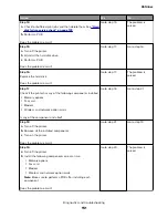
Step 1
POR the machine.
Did the control panel , fuser, fan and drive motor function at startup?
Go to step 2.
Go to step 3.
Step 2
Run some print jobs.
Does the error remain?
Go to step 3.
The problem is
solved.
Step 3
Check all cables on the controller board.
Are they connected properly?
Go to step 5.
Go to step 4.
Step 4
Properly connect all the cables on the controller board.
Does the error remain?
The problem is
solved.
Go to step 5.
Step 5
Unplug the cable JPS1 from the controller board, and verify the
following voltages from the cable:
•
+5 V at pins 11, 12, 13, 14, 15, 16
•
GND at pins 18, 20
Are the voltages correct?
Go to step 7.
Go to step 6.
Step 6
Replace the power supply.
Does the error remain?
The problem is
solved.
Contact the next
level of support.
Step 7
Is the control panel functioning properly?
Go to step 9.
Go to control panel
service check. Go to
“Control panel
service check” on
page 167
4514-6xx
Diagnostics and troubleshooting
165
Содержание M3150
Страница 12: ...Part name index 393 4514 6xx Table of contents 12 ...
Страница 20: ...4514 6xx 20 ...
Страница 38: ...4514 6xx 38 ...
Страница 172: ...4514 6xx 172 ...
Страница 233: ...c Insert the cable into the hole B d Route the cable using the new path 4514 6xx Parts removal 233 ...
Страница 246: ...3 Remove two screws A and then remove the cooling fan mount A 4514 6xx Parts removal 246 ...
Страница 256: ...5 Remove the four screws B and then remove the right front mount B 4514 6xx Parts removal 256 ...
Страница 258: ...Cartridge plunger removal 1 Open the front door 2 Tilt the cartridge plunger 4514 6xx Parts removal 258 ...
Страница 260: ...b Set the spring over the plunger 4514 6xx Parts removal 260 ...
Страница 262: ...Bezel removal MS610dn 1 Open the front door 2 Push the latches A and then remove the bezel A 4514 6xx Parts removal 262 ...
Страница 277: ...3 Squeeze the latches B to release the left and right links B 4514 6xx Parts removal 277 ...
Страница 300: ...3 Place the printer on its rear side 4 Release the sensor flag A 4514 6xx Parts removal 300 ...
Страница 301: ...5 Remove the screw B 6 Remove the sensor flag bracket C 4514 6xx Parts removal 301 ...
Страница 306: ...8 Remove the three screws A A 9 Disconnect the cable from the pick lift motor gearbox 4514 6xx Parts removal 306 ...
Страница 323: ...3 Swing the right cover backward to remove 4 Remove the screw D 4514 6xx Parts removal 323 ...
Страница 333: ...4514 6xx 333 ...
Страница 335: ...Assembly 1 Covers 4514 6xx Parts catalog 335 ...
Страница 338: ...4514 6xx Parts catalog 338 ...
Страница 339: ...Assembly 2 Electronics 1 1 2 3 4 5 7 9 10 11 6 8 12 4514 6xx Parts catalog 339 ...
Страница 342: ...4514 6xx Parts catalog 342 ...
Страница 343: ...Assembly 3 Electronics 2 4 3 2 1 5 6 8 9 7 4514 6xx Parts catalog 343 ...
Страница 345: ...4514 6xx Parts catalog 345 ...
Страница 346: ...Assembly 4 Frame 10 11 12 13 14 9 1 5 6 7 8 4 4 2 3 4514 6xx Parts catalog 346 ...
Страница 349: ...Assembly 5 Option trays 3 4 5 6 1 2 4514 6xx Parts catalog 349 ...
Страница 354: ...4514 6xx Parts catalog 354 ...
Страница 356: ...4514 6xx Parts catalog 356 ...
Страница 364: ...4514 6xx 364 ...
Страница 376: ...4514 6xx 376 ...
Страница 386: ...4514 6xx Index 386 ...
Страница 392: ...4514 6xx Part number index 392 ...
Страница 398: ...4514 6xx Part name index 398 ...

