#
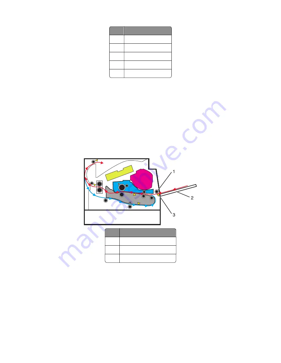
Part
1
First input roller
2
Secondary input roller
3
Separator roller
4
Pick rollers
5
Option tray
Multipurpose feeder (MPF)
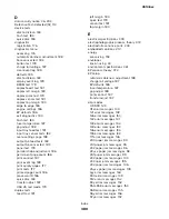
The driving force from the main drive motor is transmitted through the MPF gearbox. When the MPF solenoid
activates, it allows the MPF sector gear linked to the MPF gearbox to rotate. The MPF pick roll shaft is connected
to the MPF sector gear.
The MPF can be accessed by opening the MPF tray on the front door. In an MPF paper feed, the MPF paper
present sensor detects the media. The instant the MPF pick roll shaft rotates, the cams on each end of the shaft
disengage the MPF tray. Each side of the tray is connected to the front access cover by springs. When
disengaged from the shaft, the springs pull the tray causing the media to come into contact with the MPF pick
roller. At the same time the pick roller rotates, pushing the media to the separator pad. The media does not
pass through the secondary input roller, but directly to the first input roller.
#
Part
1
MPF pick roller
2
MPF tray
3
MPF paper present sensor
Simplex printing
Situated along the first input roller, is the deskew shutter. It subjects the media to a deskewing force based on
the media width. The direction of the force is transverse to the feed direction. The leading edge of the media
then passes though the input sensor.
After the edge of the media is aligned, the first input roller feeds the media to the transfer roll for toner transfer.
At this point, the toner image is already on the photoconductor drum surface. As the media passes between
the photoconductor drum and transfer roll, the toner image is transferred to the media.
4514-6xx
Theory of operation
366
Содержание M3150
Страница 12: ...Part name index 393 4514 6xx Table of contents 12 ...
Страница 20: ...4514 6xx 20 ...
Страница 38: ...4514 6xx 38 ...
Страница 172: ...4514 6xx 172 ...
Страница 233: ...c Insert the cable into the hole B d Route the cable using the new path 4514 6xx Parts removal 233 ...
Страница 246: ...3 Remove two screws A and then remove the cooling fan mount A 4514 6xx Parts removal 246 ...
Страница 256: ...5 Remove the four screws B and then remove the right front mount B 4514 6xx Parts removal 256 ...
Страница 258: ...Cartridge plunger removal 1 Open the front door 2 Tilt the cartridge plunger 4514 6xx Parts removal 258 ...
Страница 260: ...b Set the spring over the plunger 4514 6xx Parts removal 260 ...
Страница 262: ...Bezel removal MS610dn 1 Open the front door 2 Push the latches A and then remove the bezel A 4514 6xx Parts removal 262 ...
Страница 277: ...3 Squeeze the latches B to release the left and right links B 4514 6xx Parts removal 277 ...
Страница 300: ...3 Place the printer on its rear side 4 Release the sensor flag A 4514 6xx Parts removal 300 ...
Страница 301: ...5 Remove the screw B 6 Remove the sensor flag bracket C 4514 6xx Parts removal 301 ...
Страница 306: ...8 Remove the three screws A A 9 Disconnect the cable from the pick lift motor gearbox 4514 6xx Parts removal 306 ...
Страница 323: ...3 Swing the right cover backward to remove 4 Remove the screw D 4514 6xx Parts removal 323 ...
Страница 333: ...4514 6xx 333 ...
Страница 335: ...Assembly 1 Covers 4514 6xx Parts catalog 335 ...
Страница 338: ...4514 6xx Parts catalog 338 ...
Страница 339: ...Assembly 2 Electronics 1 1 2 3 4 5 7 9 10 11 6 8 12 4514 6xx Parts catalog 339 ...
Страница 342: ...4514 6xx Parts catalog 342 ...
Страница 343: ...Assembly 3 Electronics 2 4 3 2 1 5 6 8 9 7 4514 6xx Parts catalog 343 ...
Страница 345: ...4514 6xx Parts catalog 345 ...
Страница 346: ...Assembly 4 Frame 10 11 12 13 14 9 1 5 6 7 8 4 4 2 3 4514 6xx Parts catalog 346 ...
Страница 349: ...Assembly 5 Option trays 3 4 5 6 1 2 4514 6xx Parts catalog 349 ...
Страница 354: ...4514 6xx Parts catalog 354 ...
Страница 356: ...4514 6xx Parts catalog 356 ...
Страница 364: ...4514 6xx 364 ...
Страница 376: ...4514 6xx 376 ...
Страница 386: ...4514 6xx Index 386 ...
Страница 392: ...4514 6xx Part number index 392 ...
Страница 398: ...4514 6xx Part name index 398 ...


