


Maintenance and repair
INTORQ | BA 14.0197 | 06/2014
42
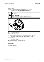
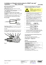
7.3.3
Release / voltage
1. Start motor and control system!
2. Observe the air gap "s
L
" when the drive is running. It should be zero.
3. Measure the DC voltage at the brake.
- After the overexcitation time (see bridge/half-wave rectivier,
32), the measured DC voltage
must correspond to the holding voltage (
33). A deviation of ±10 % is permissible.
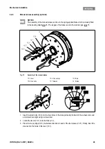
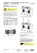
7.3.4
Replacing the rotor
1. Switch off voltage!
2. Disconnect the connection cable.
3. Loosen the screws evenly and remove them completely.
4. Remove the complete stator from the bearing shield. Pay attention to the connection cable.
5. Pull the complete rotor from the hub.
6. Check the toothing of the hub.
7. Replace the hub too if it is worn.
8. Check the friction surface on the bearing shield. In case of strong scoring at the flange, replace the
flange. In case of strong scoring on the bearing shield, rework the friction surface.
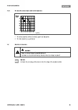
9. Measure the rotor thickness (new rotor) and head height of the sleeve bolts with a calliper gauge.
10. Calculate the distance between the stator and the armature plate as follows:
Distance = rotor thi s
LN - head height
("s
LN
"
15)
11. Unscrew the sleeve bolts evenly until the calculated distance between stator and armature plate is
reached.
12. Install and adjust the new complete rotor and stator,
24.
13. Reconnect the connection cable.
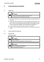
DANGER
Danger: rotating parts!
The running rotor must not be touched.
DANGER
There is a risk of injury by electrical shock!
Live connections must not be touched.
DANGER
Danger: rotating parts!
The brake must be free of residual torque.
Содержание E27 Series
Страница 4: ...4 E27 Gearless Installation and maintenance 5323 en 2018 04 c...
Страница 15: ......
Страница 46: ...30 31 NOTES...
Страница 109: ......
Страница 110: ......
Страница 111: ......


