background image


24 / 31 


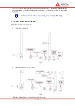
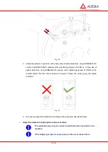
Fig. 30


3.  Clamp the detector in position. In the case of mechanical detectors, using DIN84 M2.5x10 

screws and DIN125 M2.5 washers with a tightening torque of 0.23N·m. In the case of 
optical detectors, using DIN84 M3x10 screws with a tightening torque of 0.59N·m it is 
recommended that the screw heads  be sealed.  Clamp the cable  using  the  staple 
provided. 


Fig. 31


4.  Proceed to adjust the detectors according to the procedure described below. 


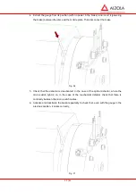
Adjust the detectors (both optical and mechanical): 


This operation may only be carried out with the brake mounted on the 

machine. 


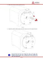
If the shipping screws (red) are present, remove or loosen them. 

Содержание E27 Series

Страница 1: ...E27 Gearless Installation maintenance Permanent magnet synchronous motor for lifts Part number 5323 en 2018 04 c...

Страница 2: ...for making this choice and would ask you to read the contents of this manual By observing a few essential rules you will ensure problem free operation for many years Moteurs Leroy Somer NOTE Leroy So...

Страница 3: ...Optional 9 5 4 Electrical connection using the cables supplied by Leroy Somer 9 5 4 1 Wiring the motor the thermal sensor and the encoder 9 5 4 2 Wiring the brakes 10 5 4 3 Earth connection 10 5 5 Det...

Страница 4: ...4 E27 Gearless Installation and maintenance 5323 en 2018 04 c...

Страница 5: ...e Mains voltage disconnected and no residual voltage present Careful examination of the causes of the stoppage jammed transmission loss of phase cut out due to thermal protection etc Even when not sup...

Страница 6: ...ION Inspect the machine as soon as it is received If there is any damage that has been caused during transportation contact immediately the carrier As soon as you receive the machine check that the na...

Страница 7: ...resistances then increase the voltage until 50 of the rated current is reached Maintain the power for 4 hours The temperature of the motor should increase slightly If the brakes are released the sheav...

Страница 8: ...5 E27M 150 0 5 E27L 170 0 5 The fixing screws not supplied must be tightened once the traction ropes and the traction sheave are perfectly aligned and once the full load is applied onto the traction...

Страница 9: ...5 N m 10 There is a high risk of jamming your fingers between the cables and the sheave 5 3 5 Optional Protection device for sheave and or brake E27 motor is available with 2 additional options Protec...

Страница 10: ...the brakes and to the appendix 1 of this manual The grounding of the cable shielding is done using the metal clamps 5 4 3 Earth connection Connect the earth using the dedicated terminals on both moto...

Страница 11: ...Black Black NO Dark blue Red Brown Blue Brake coil Blue Pink Brake coil Red Brakes cable Grey Microswitch NC Black Yellow NO Dark blue Green Brown Brown Brake coil Blue White Brake coil FOR E27S AND E...

Страница 12: ...ontacts MNL 926884 1 Black U1 Brown V1 Blue W1 Black PTC Connector MOLEX ref 39 01 3028 Contacts MOLEX s rie 5556 or TECO ELECTRIC ref 0 350777 1 Black 2a Cos 2a Cos 5b CosRef 5b CosRef 4a Sin 4a Sin...

Страница 13: ...ing down acknowledging insulation faults and protection against overcurrents The table above is given for information only and must under no circumstances be used in place of the current standards The...

Страница 14: ...8 MAINTENANCE 8 1 Bearings The bearings do not require any maintenance as they are greased for life 8 2 After one month s operation Check that the screws and electrical connections are correctly tight...

Страница 15: ......

Страница 16: ...Moteurs Leroy Somer Headquarter Boulevard Marcellin Leroy CS 10015 16915 ANGOUL ME Cedex 9 Limited company with capital of 65 800 512 RCS Angoul me 338 567 258 www leroy somer com...

Страница 17: ...1 31 DATE OF CREATION 18 03 2013 REACH EVO 01 EVO 05 DATE OF REVIEW 25 10 2016 REVIEW ES10 INSTALLATION MANUAL FOR EVO BRAKES...

Страница 18: ...lation 8 3 4 Screw torques 9 3 5 Shipping screws 9 3 6 Positioning the rubber dust cover 10 3 7 Positioning the manual release lever 11 4 ELECTRIC INSTALLATION 16 4 1 Before starting 16 4 2 Tools 16 4...

Страница 19: ...family belongs to the compression spring type of brakes In the absence of an electric current springs located in their casing exercise a force on the mobile plates that stops the movement of the fric...

Страница 20: ...tectors micro switches 6 Fixing screws 7 Manual release lever 8 Shipping screws 9 Cables Table 1 2 2 Labelling All ALZOLA brakes belonging to the EVO family incorporate two labels In the first are mar...

Страница 21: ...im K Dim L Dim M Dim N EVO 01 238 213 185 138 114 18 80 17 22 48 120 0 65 35 EVO 02 275 245 225 184 173 2 18 90 17 22 47 120 0 65 35 EVO 03 300 272 5 250 184 142 20 90 17 23 53 125 5 65 40 EVO 04 348...

Страница 22: ...Sound Level dB 55 dB A a 1 m Maximum ambience Temp C 40 Maximum voltage to operate detectors micro switches 30 VDC Mechanical detector 24 VDC Optical detector Maximum intensity for detectors micro swi...

Страница 23: ...orization of ALZOLA as with any use not complying with the technical specifications set by ALZOLA shall lead to the suppression of the Warranty and the annulment of ALZOLA s liability with regard to t...

Страница 24: ...the friction material support surfaces Danger Deficient cleaning of the braking surfaces may lead to a decrease in the brake torque We recommend the use of Loctite 7063 or similar Procedure Apply the...

Страница 25: ...n hubs being displaced and the corresponding transmission of the braking torque to the fixing screws with the risk of them shearing An excessive tightening may also jeopardise the safety of the brake...

Страница 26: ...sing the lift to fall Fig 6 After being removed it is convenient to place the caps supplied with the brake to avoid the insertion of particles in the inside of the brake If the brake incorporates Bowd...

Страница 27: ...e brake Precaution It is not prepared to prevent penetration by liquids Optical detectors must be covered as they are sensitive to dirt and light 3 7 Placement of the manual release lever Types of lev...

Страница 28: ...installation was required by the client the following procedure should be observed Following a mechanical and electric installation of the brake 1 Remove the central caps from the brake Fig 10 2 Lubri...

Страница 29: ...in one of the open holes after removing the caps Fig 12 4 Turn this screwing the end in the mobile plate as far as it will go The right hand lever is screwed in clockwise and the left hand lever is s...

Страница 30: ...le on the other side screwing in the opposite direction Fig 15 Check that both hubs have one of their three holes on the upper side Otherwise extract the hub turn it slightly and relocate it Repeat th...

Страница 31: ...15 31 Fig 16 7 Mount the bolt DIN 985 M8 release nut and the washer onto the handles Fig 17 8 Position the handles appropriately and clamp them with DIN7991 M6x12 screws Fig 18...

Страница 32: ...Bowden release levers we recommend removing the screws Fig 19 To simplify the manual lever assembly process in circumstances where this operation has to be repeated on numerous occasions ALZOLA may m...

Страница 33: ...that the Voltage in the grid is suited to the brake consult the characteristics label EVO brakes consist of two independent electric circuits They must be connected according to the following diagram...

Страница 34: ...the brake casing releasing the disc and allowing movement of the machine axle Immediately disconnect the brake if you should observe The brake produces a loud noise during connection disconnection The...

Страница 35: ...haracteristics 6 1 Air gap verification Under normal operations gearless machine brakes only carry out static braking except for emergency stops That is why under normal working conditions there shoul...

Страница 36: ...s or light in the case of optical micro switches in the detector Exposing of the microswitches to silicon gas may cause their dysfunction 6 3 Winding verification Checking the resistance Check that th...

Страница 37: ...cabin and the counterweight Danger of entrapment Carrying out this process may require prior withdrawal of the encoder and subsequent assembly and readjustment 1 Once the installation has been secured...

Страница 38: ...holes insert the initially removed caps again 7 Following the disc replacement check the detectors work correctly section 6 2 adjust them if necessary section 7 2 7 2 Replacement and adjustment of de...

Страница 39: ...ctuator screw which will require the readjustment of the detector or may be due to the detector breaking which will require it to be replaced Below is a description of both processes Replacement of de...

Страница 40: ...4 M3x10 screws with a tightening torque of 0 59N m it is recommended that the screw heads be sealed Clamp the cable using the staple provided Fig 31 4 Proceed to adjust the detectors according to the...

Страница 41: ...r Connect the brake to the current Fig 32 Loosen the locknut and move the adjusting screw until the point where the detector is active In the case of optical detectors the red light will switch off In...

Страница 42: ...26 31 2 Then tighten the locknut of the adjusting screw Fig 34 3 Activate and deactivate the brake repeatedly even with the gauge in the previous position it works correctly Fig 35...

Страница 43: ...e brake Fig 36 5 Check that the detector is deactivated In the case of the optical detector where the micro switch light is on In the case of the mechanical detector check that there is continuity bet...

Страница 44: ...acement of the manual release lever 1 Extract the lever to be replaced by turning it so that is goes away from the opposite lever Fig 38 Remember that the threading of each lever is in the opposite di...

Страница 45: ...act in the case of an emergency stop The brake is connected to an alternating current Connect to the direct current The brake does not release Particles stop the casing from moving Replace brake The t...

Страница 46: ...30 31 NOTES...

Страница 47: ...31 31 TRANSFORMATIONS ELECTROMEC NICAS ALZOLA S L C Uzbina n 11 Pol Jundiz 01015 Vitoria Gasteiz SPAIN 34 945 291 679 34 945 291 677 lae alzolasl net www alzolasl net...

Страница 48: ...www intorq com setting the standard www intorq com INTORQ BFK464 Electromagnetically released spring applied brake Operating Instructions...

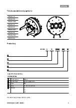
Страница 49: ...b bore options BFK464 17S BFK464 18S BFK464 18S 2 BFK464 19S BFK464 20S BFK464 20S 1 BFK464 25S BFK464 25S 1 BFK464 28S INTORQ B FK A A B C D D E Legend for the product key INTORQ BFK464 Product group...

Страница 50: ...No Rated torque Date of manufacture Material number Version Description 13348276 1 0 09 2010 TD09 First edition 33000116 2 0 11 2010 TD09 Enlarged to include 19S and 28S sizes Supplement of the table...

Страница 51: ...Rating design data 17 3 4 Switching energy operating frequency 18 3 5 Emissions 19 4 Mechanical installation 20 4 1 Important notes 20 4 2 Necessary tools 20 4 3 Assembly 21 4 4 Installation procedure...

Страница 52: ...be in a complete and perfectly readable condition 1 2 Terminology used 1 3 Conventions in use This document uses the following styles to distinguish between different types of information Term In the...

Страница 53: ...oil resistance at 20 C Sh 1 h Operating frequency the number of switching operations evenly spread over the time unit Shue 1 h Transition operating frequency thermal parameter of the brake Shzul 1 h M...

Страница 54: ...and important safety in formation Safety instructions Structure of safety instructions SIGNAL WORD Icon Indicates the type of danger Signal word Characterises the type and severity of danger Note Desc...

Страница 55: ...ficiencies or incomplete deliveries immediately to INTORQ GmbH Co KG 1 7 Disposal The spring applied brake consists of different types of material Recycle metals and plastics Ensure professional dispo...

Страница 56: ...ally 1 9 Legal regulations Liability The information data and notes in these Operating Instructions met the state of the art at the time of printing Claims referring to drive systems which have alread...

Страница 57: ...t characteristics Only qualified skilled personnel are permitted to work on and with INTORQ components According to IEC 60364 or CENELEC HD 384 qualified skilled personnel are persons who are familiar...

Страница 58: ...operated beyond their corresponding power limits Any other use or excessive usage shall be deemed improper Applications of the INTORQ spring applied brake Air humidity no restrictions If condensation...

Страница 59: ...urfaces The braking torque is ap plied through two separate braking circuits both electrical and mechanical via several compression springs 1 2 in the form of generated friction The brake circuits are...

Страница 60: ...on linings ensure high braking torque and low wear The braking torque is transmitted between the hub 4 and the rotor 3 via gear teeth 3 1 3 Brake release When the brakes are applied an air gap sL is p...

Страница 61: ...his will reduce the switching noises 3 1 8 Project planning notes The brakes are dimensioned in such a way that the given rated torques are reached safely after a short run in process However as the o...

Страница 62: ...complete sLN 0 05 mm sLmax mm mm min mm max mm m kg BFK464 17S 0 4 0 6 0 2 12 7 13 12 BFK464 18S 0 4 0 6 0 2 12 7 13 15 BFK464 18S 2 0 4 0 6 0 2 12 7 13 14 5 BFK464 19S 0 4 0 6 0 2 15 7 16 18 8 BFK46...

Страница 63: ...0S 1 230 M10 6 x M10x100 6 x M10x110 19 18 48 48 BFK464 25S 278 M10 6 x M10x110 6 x M10x1301 18 22 5 48 71 BFK464 25S 1 278 M10 6 x M10x110 6 x M10x1301 18 22 5 48 71 BFK464 28S 314 M16 6 x M16x120 6...

Страница 64: ...que MK Rated torque U Voltage Type Rated torque1 Max perm switching energy Transitional switching frequency Operating times ms at sLN and 0 7 IN 2 Max speed4 MK QE Shue Engaging DC side3 Disengag ing...

Страница 65: ...the drive system is operated with a frequency inverter so that the brake will not be deenergised before the motor is at standstill AC switching is also possible not applicable to emergency braking In...

Страница 66: ...ge Heat Since the brake converts kinetic energy as well as mechanical and electrical energy into heat the surface temperature varies considerably depending on the operating conditions and possible hea...

Страница 67: ...ket Allen screws Open jawed spanner Allen key for transport safety bolts Sleeve bolts Manual release nuts Measuring range Nm Width across flats mm Width across flats mm Width across flats mm BFK464 17...

Страница 68: ...spring applied brake 2 Check for completeness 3 Check the name plate data especially the rated voltage 4 3 3 Overview Brake size Minimum requirements Use as counter friction surface Material1 Evenness...

Страница 69: ...haft 3 Secure the hub against axial displacement for example by using a circlip 4 2 NOTICE The toothed hub and screws must not be lubricated with grease or oil NOTICE When you have ordered a version w...

Страница 70: ...iction face Fig 5 Assembly without counter friction face Install the counter friction faces Fig 6 Assembly of the flange 1 Hold the flange 6 to the end shield 15 2 Align the through holes in the flang...

Страница 71: ...manufacturer In the following sections only assembly for the versions with flange will be described Assembly of the complete stator Fig 8 Mounting the complete stator 1 Push the complete stator 1 onto...

Страница 72: ...sing a feeler gauge and compare the values to the values for sLN in the table 15 If sL 15 is not within the tolerance readjust the air gap Air gap sL 1 1 Stator 6 Flange 10 Cylinder head bolt 2 Armatu...

Страница 73: ...4 Check the air gap sL near the bolts 10 with a feeler gauge sLN 15 5 Repeat the adjustment procedure if the deviation of sLN is too large WARNING Danger rotating parts Switch off the voltage The dri...

Страница 74: ...ANGER Brake may fail If the manual release is not adjusted correctly the brake may fail Possible consequences Severe injuries or material damage Protective measure Ensure that the dimension s is obser...

Страница 75: ...2 Locate the levers 12 1 onto the brake 14 3 Place four cup springs 12 6 in alternate directions in each of the four sleeves 12 7 Finally insert the sleeves into the holes in the lever 12 1 NOTICE The...

Страница 76: ...sLN 15 if required The brake is not energised during adjustment 1 1 Stator complete 6 Flange 12 1 Lever 2 Armature plate Type sLN 0 05 mm s 0 1 mm BFK464 17S 0 4 5 3 BFK464 18S BFK464 18S 2 BFK464 19S...

Страница 77: ...rresponds to the name plate data NOTICE If an emergency stop is carried out without the required suppressor circuit the control unit may be destroyed Observe the correct polarity of the suppressor cir...

Страница 78: ...same time 5 2 Bridge half wave rectifiers optional BEG 561 The bridge half wave rectifiers are used to supply electromagnetic DC spring applied brakes which are ap proved for the use with such rectif...

Страница 79: ...464 20S 1 BEG 561 255 130 BFK464 25S BEG 561 255 130 BFK464 25S 1 BEG 561 255 130 BFK464 28S BEG 561 440 030 1 400 10 360 180 BFK464 17S BEG 561 440 030 1 BFK464 18S BEG 561 440 030 1 BFK464 18S 2 BEG...

Страница 80: ...ge rectification 0 9 x U1 Output voltage for half wave rectification 0 45 x U1 Ambient temperature storage operation C 25 70 Type Input voltage U1 40 Hz 60 Hz Max current Imax Overexcitation time t 20...

Страница 81: ...heat dissipation 2 For other assembly e g adhesive 5 3 Electrical connection DANGER There is a risk of injury by electrical shock The brake must only be electrically connected when no voltage is appli...

Страница 82: ...breakaway torque is common in particular after long downtimes in humid environments where temperatures vary Check the braking torque if the brake is inserted on the customer s friction surfaces If the...

Страница 83: ...to the holding voltage see table 5 A deviation of 10 is permissible 7 Check the air gap sL It must be zero and the rotor must rotate freely 8 Check the switching status of the microswitch see table 6...

Страница 84: ...must be able to be turned freely A low residual torque is permitted 15 Release the lever Torque must be available The preparations for commissioning are completed 6 3 Commissioning 1 Switch on drive s...

Страница 85: ...Measure the DC voltage at the brake The measured DC voltage after the overexcitation time see bridge half wave rectifier 32 must correspond to the holding voltage see table 5 A deviation of 10 is perm...

Страница 86: ...E Braking torque reduction The air gap must not be re adjusted after it has been correctly adjusted during the initial installation of the brake on the motor This could result in a loss of braking tor...

Страница 87: ...g conditions and brake loads must be de fined for every application For the spring applied brakes the maintenance intervals and maintenance oper ations listed in the table below must be followed The m...

Страница 88: ...escription see 42 NOTICE Brakes with defective armature plates socket head cap screws springs or counter friction faces must always be replaced completely Generally observe the following for inspectio...

Страница 89: ...Replace the hub too if it is worn 8 Check the friction surface on the bearing shield In case of strong scoring at the flange replace the flange In case of strong scoring on the bearing shield rework t...

Страница 90: ...rder Order number of the brake Position number of the spare part Fig 17 Spring applied brake BFK464 S S 1 S 2 Item Designation Variant 1 Stator complete Voltage 3 Complete rotor Rotor complete noise r...

Страница 91: ...m 100 1000 mm in 100 mm steps from 1000 2500 mm in 250 mm steps Manual release mounted Armature plate Standard Microswitch Monitoring the switching function Switching noises Damped Rotor Aluminium Noi...

Страница 92: ...alues see 15 If resistance is too low replace the complete stator Check the coil for short to ground using a multimeter If there is a short to ground replace the complete stator Check the brake voltag...

Страница 93: ...26 Rotor thickness too small Rotor has not been replaced in time Replace the rotor 42 Voltage is not zero during the functional test chap 6 2 Microswitch incorrectly wired Check and correct the wirin...

Страница 94: ...Release Monitoring Page 12 Wear Monitoring Page 13 Electrical Connection Operation with Nominal Voltage Page 14 Electrical Connection Operation with Overexcitation Page 15 Brake Inspection Customer si...

Страница 95: ...ess of the mechanical dual circuit system can be tested at the place of operation requirement acc TRA 102 Guidelines for Electromagnetic Compatibility EMC In accordance with the EMC directives 2004 10...

Страница 96: ...contactable metal parts Protect against highly inductive switch off peaks by installing varistors spark quenching units or similar devices according to VDE 0580 2000 07 Paragraph 4 6 to prevent damag...

Страница 97: ...e 1 Fax 08341 804 421 D 87665 Mauerstetten http www mayr de Page 4 of 15 Germany eMail info mayr de Fig 1 Fig 2 Fig 3 Fig 4 5 2 4 4x 1 1 1 6 12 1 1 6 6 5 9 4x 14 8x 1 13 Brake 1 Brake 2 1 2 3 2 8 Cust...

Страница 98: ...ig 9 page 11 6 2 Cap screw Fig 9 page 11 6 3 Hexagon nut Fig 9 page 11 6 4 Hexagon head screw Fig 9 page 11 6 5 Spring washer Fig 9 page 11 6 6 Microswitch cable 3 x AWG20 black blue brown 7 Hand rele...

Страница 99: ...the device wearing down to an air gap of 0 9 mm unnoticed we recommend mounting a wear monitoring device available on request When the air gap reaches a 2 0 mm design with hand release or a 2 5 mm de...

Страница 100: ...1 DC Drop out t1 DC 90 Nm 145 250 570 35 140 120 Nm 170 200 510 27 125 150 Nm 200 150 450 20 110 150 150 Nm Approx 120 120 Nm 170 420 980 75 230 160 Nm 225 310 790 53 195 200 Nm 280 190 620 30 160 200...

Страница 101: ...N 42955 Larger deviations can lead to a drop in torque to continuous slipping on the rotor 3 and to overheating The toothed motor shaft Type 8012 _0_ _3 should be designed according to the information...

Страница 102: ...ews using a torque wrench and observe the tightening torque acc Table 3 4 Check air gap a 0 45 2 0 05 0 mm Fig 3 The nominal air gap must be in the horizontal centre axis area on both armature disks 2...

Страница 103: ...armature disk 2 are pulled against the coil carrier 1 Fig 6 The rotor 3 is then free thus releasing the brake Table 5 Technical Data Release force per braking circuit with Size Braking torque Bowden...

Страница 104: ...hexagon nut 6 3 so that the hexagon head screw 6 4 is placed under pre tension by the spring washer 6 5 3 Put a feeler gauge 0 12 mm loose sensor plate between the switch tappet and the hexagon head s...

Страница 105: ...ch Specifications 15 1 Characteristic values for measurement 250 V 3 A Minimum switching capacity 12 V 10 mA DC 12 Recommended switching capacity for maximum lifetime and reliability 24 V 10 50 mA DC...

Страница 106: ...times are influenced by the temperature and the air gap between the armature disk 2 and the coil carrier 1 dependent on the wear condition of the linings Magnetic Field Build up When the voltage is s...

Страница 107: ...is also delayed Field Build up with Overexcitation A quicker and safer drop in braking torque is achieved if the coil is temporarily placed under a higher voltage than the nominal voltage as the curr...

Страница 108: ...shorter than the stopping distance for an individual circuit Maintenance ROBA twinstop brakes are mainly maintenance free The friction linings are robust and wear resistant This ensures a particularl...

Страница 109: ......

Страница 110: ......

Страница 111: ......

Страница 112: ...Moteurs Leroy Somer Headquarter Boulevard Marcellin Leroy CS 10015 16915 ANGOUL ME Cedex 9 Limited company with capital of 65 800 512 RCS Angoul me 338 567 258 www leroy somer com...

Отзывы: