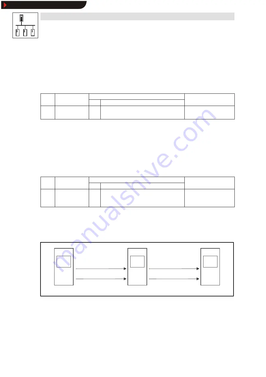
System bus (CAN) with Servo PLC & Drive PLC
Configuration (FIF interface)
5-2
l
PLC-Systembus EN 1.1
Delay time for system bus initialisation (boot-up)
Some bus participants (e.g. HMIs) need a certain start-up time after power-on before they can
accept NMT commands from the master to switch to
operational.
You can set a delay time to be observed after power-on before NMT commands are transmitted to
ensure that all bus participants, even the one with the longest start-up time, are really ready to
receive the NMT commands.
•
The delay time is configured via code C2456/1:
Code
LCD
Possible settings
Info
Lenze Choice
C2456/1 CAN1 boot up
3000
0
{1 msec}
65000 Delay time after power-on for
initialisation through the “quasi”
master
5.3
Node address (node ID)
A so-called node address in the range from 1 to 63 (also called
node ID) is assigned to each
participant part of the system bus network.
•
Each node address may only be assigned once.
•
The node address for the FIF interface of the PLC is configured via code C2450:
Code
LCD
Possible settings
Info
Lenze Choice
C2450 CAN1 address
1
1
{1}
63 System bus node address
•
Save changes with C0003 = 1
•
Changes will only become
effective after a reset node!
Assigning the node address for data exchange between Lenze controllers
If the node addresses are assigned in continuous, ascending order to the Lenze controllers, the
default setting of the event-controlled data object identifiers (FIF_CAN2_IO/FIF_CAN3_IO) allows
communication between the controllers:
L
Node-ID 1
FIF-CAN2_OUT
FIF-CAN2_IN
FIF-CAN3_OUT
FIF-CAN3_IN
L
Node-ID 2
FIF-CAN2_OUT
FIF-CAN2_IN
FIF-CAN3_OUT
FIF-CAN3_IN
L
Node-ID 3
Show/Hide Bookmarks
Содержание 9300 Servo PLC
Страница 1: ...L Global Drive System bus CAN with 9300 Servo PLC Drive PLC Manual Show Hide Bookmarks...
Страница 38: ...System bus CAN with Servo PLC Drive PLC Configuration 3 12 l PLC Systembus EN 1 1 Show Hide Bookmarks...
Страница 112: ...System bus CAN with Servo PLC Drive PLC Index 10 4 l PLC Systembus EN 1 1 Show Hide Bookmarks...


