CANopen
4
Installation
4-4
L
BA2175 EN 2.0
4.3.2
Voltage supply
If necessary, supply the 2175 fieldbus module via the plug-in contacts V+/V-
(
^
4-3)
using a separate
voltage supply of 24 V DC
±
10 % .
820X controllers always require a separate voltage supply.
Use a separate supply unit in every control cabinet if the distance between the control cabinets is
larger than normal.
Controller
External voltage supply
820X
always required
821X / 822X / 824X and 93XX
Only necessary if the mains which supply the corresponding controllers is to be switched off but
communication must not be interrupted.
8200 vector
see below
Chapter 4.4 describes how to connect the 2175 fieldbus module to the bus system.
Note!
Internal voltage supply of the fieldbus module connected to a 8200 vector
(only applies to controllers as of nameplate data 82EV 1x 1x)
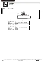
Controllers with an extended AIF interface (front of the 8200 vector) can be internally supplied. The
part of the drawing highlighted in grey shows the jumper position.
With Lenze setting, the fieldbus module is not internally supplied.
For internal voltage supply, put the jumper in the position indicated below.
Lenze setting
(only external voltage supply)
Internal voltage supply
4.3.3
Wiring to a host
Warning!
An additional electrical isolation is required if
•
a 820X, 821X or 8200 vector controller is connected to a host
•
a safe electrical isolation (double basic insulation) to VDE 0160 is required.
For this, you can use an interface module for the host with an additional electrical isolation
(see the corresponding manufacturer’s information).
For wiring, the electrical isolation of the supply voltage must be taken into account. The supply
voltage is assigned to the same potential as the data bus.
Phone: 800.894.0412 - Fax: 888.723.4773 - Web: www.actechdrives.com - Email: [email protected]
Show/Hide Bookmarks


