The failing system board must be returned with a microprocessor socket cover to protect the pins during
shipping and handling.
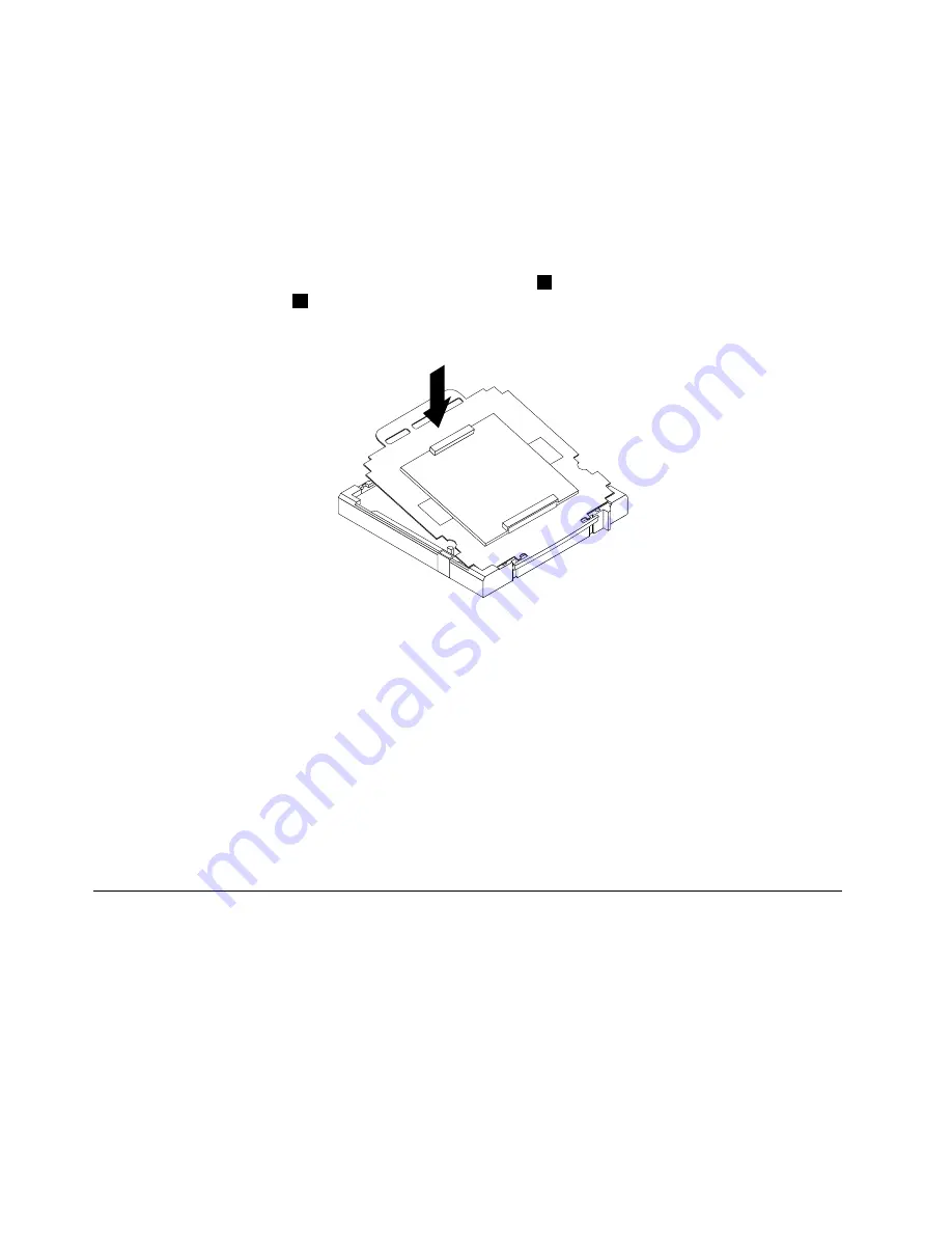
To install the microprocessor socket cover, do the following:
1. Release the lever securing the microprocessor retainer and open the retainer to access the
microprocessor.
2. Grasp the microprocessor on the sides and lift it straight up and out of the socket. Do not touch the
contacts on the microprocessor socket.
3. Note the orientation of the socket cover. Align the notches
1
on the microprocessor socket cover
with the alignment keys
2
on the microprocessor socket. Install one side of the socket cover into
the microprocessor socket.
Figure 42. Installing one side of the socket cover into the microprocessor socket
Note:
Your microprocessor socket and cover might look slightly different from the illustration.
4. Carefully press the other side of the socket cover downwards until the socket cover snaps into place.
5. Carefully check the four corners of the socket cover to make sure that the cover is secured in the
microprocessor socket.
6. Lower the microprocessor retainer, and then lower the lever to secure the retainer. Make sure the
lever is locked into position.
7. Follow any additional instructions included with the replacement part you received.
Note:
If your system board has two microprocessor sockets, be sure to install a socket cover for each
microprocessor socket.
Replacing the LCD panel
Attention
Do not open your computer or attempt any repair before reading and understanding the “Important safety
information” in the
Safety, Warranty, and Setup Guide
that came with your computer. To obtain a copy of the
Safety, Warranty, and Setup Guide
, go to:
http://www.lenovo.com/support
This section provides instructions on how to replace the LCD panel.
To replace the LCD panel, do the following:
102
ThinkCentre Edge Hardware Maintenance Manual
Содержание ThinkCentre Edge 92z
Страница 2: ......
Страница 8: ...2 ThinkCentre Edge Hardware Maintenance Manual ...
Страница 15: ...Chapter 2 Safety information 9 ...
Страница 16: ... 18 kg 37 lbs 32 kg 70 5 lbs 55 kg 121 2 lbs 1 2 PERIGO 10 ThinkCentre Edge Hardware Maintenance Manual ...
Страница 19: ...Chapter 2 Safety information 13 ...
Страница 20: ...1 2 14 ThinkCentre Edge Hardware Maintenance Manual ...
Страница 21: ...Chapter 2 Safety information 15 ...
Страница 27: ...Chapter 2 Safety information 21 ...
Страница 31: ...Chapter 2 Safety information 25 ...
Страница 38: ...32 ThinkCentre Edge Hardware Maintenance Manual ...
Страница 62: ...56 ThinkCentre Edge Hardware Maintenance Manual ...
Страница 68: ...62 ThinkCentre Edge Hardware Maintenance Manual ...
Страница 81: ...Figure 13 Reinstall the rubber on the foot stand Chapter 9 Replacing FRUs 75 ...
Страница 116: ...110 ThinkCentre Edge Hardware Maintenance Manual ...
Страница 120: ...114 ThinkCentre Edge Hardware Maintenance Manual ...
Страница 125: ......
Страница 126: ......


