background image

25

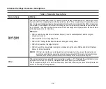
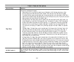
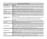
Table 6. Parameter Descriptions

Parameter Name

Definition

Stage 2 HP Lock Temp

The User shall be able to select the STG 2 HP lock temp from 40F, 45F, 50F, 55F or OFF. The value is used 

in dual fuel algorithm to lock the second stage of compressor .The default is OFF which means it is disabled 

and is not used in dual fuel algorithm. If system has only 1st stage equipment, this item is hidden from installer 

screen. For more information see “Stage 2 HP Lock Temp” on page 28.

Feels Like

This feature will display the home temperature based on a combination of inputs. Feels Like uses outdoor 

temperature, indoor temperature, and indoor humidity to determine the “feels like” condition of the home.

Wider Set Point Range

By default your thermostat operates within a range of 60-90°F. Enabling this options changes the range to 

44-99°F.

Heating Mode: Normal 

or Comfort

Options are Normal and Comfort. Default is Normal. When changing to Comfort Mode, several parameters 

are automatically modified for optimal system operations. The changed parameters are listed on the screen 

when set to Comfort.
•  Normal - This setting cools the home to the desired temperature setting. Once second-stage is activated 

by timer or differential, it will not stage down to first-stage until the next heating cycle demand.

•  Comfort - This is when the system could automatically stage up or down based on the current load 

demand.

Smart Away

This setting when enabled controls the temperature in the home when no one is home. For this to function, the 

Lennox Mobile app needs to be installed on a mobile device.

Low Balance Point

(Multistage Heat Pump Model only) -The default is 25°F. This option will only be available if an outdoor sensor 

is installed. If the outside temperature is below the programmed Low Balance Point, then the compressor stage 

operation is disallowed. This protects the compressor from operation and damage in cold outdoor tempera-

tures. Also, if the heat pump is not effective at a low outdoor temperature, then it is more comfortable and effi

-

cient to go directly to the second stage. Low Balance Point can be disable in this screen. When this is enable, 

the options are from –40°F to (the High Balance Point temperature -2) in 1.0°F steps. 

High Balance Point

The default is 50°F. This option is only available if an outdoor sensor is installed. If the outside temperature is 

above the High Balance point, then the auxiliary heat stage is disallowed. This prevents the more expensive 

auxiliary heat stage from operating, and forces the more efficient heat pump to satisfy the demand. High 

Balance Point can be disable in this screen. When this is enable, the high balance point range is from (the low 

balance point + 2) up to 75°F.

Deadband

The deadband setting is the minimum difference between the cooling and heating setpoints. This setting is 

used in auto-changeover to ensure smooth equipment operation. It also allows for flexibility of Humiditrol oper

-

ation. The default deadband is 3 and the deadband is adjustable from 3 to 9

°

F degrees.

Содержание iComfort M30

Страница 1: ...507739 02 6 2021 Supersedes 3 2020 iComfort M30 Smart Thermostat Installation and Setup Guide Disponible en español en www LennoxPros com ...

Страница 2: ...12 Advanced Settings 14 Advanced Settings Parameter Descriptions 22 Stage Control 26 Wi Fi Connection 30 Connecting to Visible Home Wi Fi Access Point 31 Connecting to Hidden Home Wi Fi Access Point 32 Wireless Terminology 32 Wireless Connectivity Troubleshooting Tips 32 Determining Wireless Connection Signal Strength 33 Alert Codes 34 Alert Code Types 34 System Test Modes 39 Save Energy Default 4...

Страница 3: ...rovides a 5 minute delay between heating or cooling cycles to prevent the compressor from being damaged NOTE There is an option in advanced settings that will allow this safety feature to be disabled By default it is set to ON Short Cycle protection is disabled during testing of the outdoor unit It is automatically reset once the test is completed WARNING Improper installation adjustment alteratio...

Страница 4: ...ent number of stages and any accessories being installed This thermostat is a 24VAC low voltage thermostat and requires a common wire to the thermostat to operate Shut off all power to system components before installing thermostat Make sure that all wiring conforms to local and national building and electrical codes and ordinances Never short jumper across terminals on the gas valve or at the sys...

Страница 5: ... affected by Drafts or dead spots behind doors and in corners Building entrances or automatic doors Heat generating equipment such as kitchen equipment Hot or cold air from ducts Radiant heat from sun or appliances Concealed pipes and chimneys Non heated non cooled areas such as an outside wall behind the thermostat 4 Run thermostat wiring from indoor unit to location where thermostat will be inst...

Страница 6: ...el to allow for proper alignment 2 Drill 3 16 5 mm holes in wall for provided wall anchors Insert provided wall anchors into drilled holes 3 Remove back plate from main thermostat assembly using a flat head screw driver 4 Route thermostat and outdoor temperature sensor optional wiring from wall through center openings on wall plate use is optional and back plate Wall Plate optional Thermostat Back...

Страница 7: ...ply and need a set of dry relay contacts then the jumper will need to be removed from R2 ACC1 R2 This is the secondary 24VAC power source for ACC Accessory The R2 terminal is connected to the ACC1 terminal by factory provided jumper Table 1 Terminal Designations Terminal Purpose D H This terminal is for an optional dehumidifier or hu midifier The D H terminal is powered using the HVAC sys tem s 24...

Страница 8: ...g Diagrams For system diagrams see the included fold out iComfort M30 Smart Thermostat System Diagrams sheet Connecting Thermostat Wiring Use Table 1 Terminal Designations on page 7 for connecting the thermostat wiring to the back plate terminals If this is a replacement thermostat connect to terminals as noted when removing the old thermostat If terminals were different on old thermostat use Tabl...

Страница 9: ...nd 3rd 4th 1st 2nd 1st 2nd HP No Heat 1 0 1 1 Y1 Y1 2 0 2 2 Y1 Y1 Y2 Y1 Y1 Y2 Gas Oil 1 1 2 1 Y1 W1 W1 Y1 1 2 3 1 Y1 W1 W1 W2 W1 W1 W2 Y1 2 1 3 2 Y1 Y1 Y2 W1 W1 Y1 Y1 Y2 2 2 4 2 Y1 Y1 Y2 W1 W1 W2 W1 W1 W2 Y1 Y1 Y2 Elec 1 1 2 1 Y1 Y1 W1 W1 Y1 1 2 3 1 Y1 Y1 W1 Y1 W1 W2 W1 W1 W2 Y1 2 1 3 2 Y1 Y1 Y2 Y1 Y2 W1 W1 Y1 Y1 Y2 2 2 4 2 Y1 Y1 Y2 Y1 Y2 W1 Y1 Y2 W1 W2 W1 W1 W2 Y1 Y1 Y2 ...

Страница 10: ...at Stages Cool Stages Heat Stage EM Heat Stage Cool Stage 1st 2nd 3rd 4th 1st 2nd 1st 2nd A C No Heat 1 0 1 Y1 2 0 2 Y1 Y1 Y2 Gas Oil or Elect 1 1 1 1 W1 Y1 1 2 2 1 W1 W1 W2 Y1 2 1 1 2 W1 Y1 Y1 Y2 2 2 2 2 W1 W1 W2 Y1 Y1 Y2 No OU Gas Oil or Elect 0 1 1 0 W1 0 2 2 0 W1 W1 W2 OU Outdoor Unit Elect Electrical Heat ...

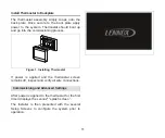
Страница 11: ... commissioning process Figure 1 Installing Thermostat If power is applied and the thermostat screen remains off inspect and verify all wire connections Commissioning and Advanced Settings After power is applied to the thermostat for the first time it displays the Lennox splash screen The Installer is then presented with the several Setup Screens to configure the system prior to operation ...

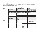
Страница 12: ...D Number Enter id Installer can add the dealer number and phone number using the key board tool Dealer Phone Number Enter phone Name email website dealer address address1 address2 city state and zip postal code GENERAL Language English Français Español Country Region United States Canada Australia Date and Time Time Adjust the date and time using the set date and set time tools Date Time Zone Atla...

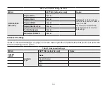
Страница 13: ...INAL SETTINGS See Terminal Settings on page 21 SYSTEM SETUP See System Setup on page 14 OUTDOOR SENSOR See Outdoor Sensor on page 16 HUMIDITY Humidity Control Off Humidify Dehumidify Dehumidification Control Center Normal or Max Displayed if Dehumidify is selected Overcooling 2F Display if Max is enabled Dehumidification Set Point 50 Displayed if Dehumidify is selected adjustable 40 to 60 ...

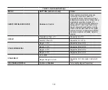
Страница 14: ...creen to input custom date settings Replace Filter 2 Disabled Replace UV Bulb Disabled Replace Humidifier Pad Disabled PureAir Maintenance Disabled Maintenance Reminder Disabled Advanced Settings Table 5 Advanced Settings on page 14 list the menu options and parameters that can be set under the Advance Settings menu option Table 5 Advanced Settings MENU SETTING default is bold Notes SYSTEM SETUP V...

Страница 15: ... C Unit 1 Stage HP Unit 2 Stage HP Unit Outdoor Unit Capacity 36 kBtu Adjustable 18 to 60 kBu Outdoor Unit 1st Stage Capac capacity Adjustable 30 to 100 Default is 70 This setting is only available if outdoor unit is 2 stage Indoor Unit Type Not Installed 1 Stage Electric 2 Stage Electric 1 Stage Oil 2 Stage Oil 1 Stage Gas 2 Stage Gas ...

Страница 16: ...aximum overcooling of two degrees above the heating set point or 65 F is represented by MAX Halfway between is represented by MID The default is MAX OUTDOOR SENSOR Yes or No Required for high and low balance points options RESIDUAL COOL 0 30 60 90 120 seconds 300 5 minute delayed BALANCE POINT Disabled or Enabled When enabled Setting used to prevent the heat pump from heating the structure The out...

Страница 17: ...Weather is enabled for this feature to operate Modifying this setting here will also change the feature status on the user settings screen Normal This setting cools or heats the home to the desired temperature setting Feels Like is OFF Comfort This setting cools or heats the home to the desired temperature setting Feels Like is ON When set to ON other parameters are modified to optimal settings fo...

Страница 18: ...ressor based heating or cooling With Smooth Set Back disabled the system will start a recovery at the programmed time Options are enabled or disabled Default is enabled OFFSET Temperature Offset 0 F Adjustable 5 to 5 F Humidity Offset 0 Adjustable 10 to 10 STAGE DIFFERENTIAL Stage 1 1 0 F Adjustable 0 5 to 8 0 F Stage 2 1 0 F Adjustable 0 5 to 8 0 F Stage 3 0 5 F Adjustable 0 5 to 8 0 F Stage 4 0 ...

Страница 19: ... Point Limit Default is 55 F Range is 45 F to 80 F VCM ASHRAE and Ventilation Outdoor Condition Override is set to ENABLED NOTE In this mode the thermostat can assist the installer by validating the ventilation CFMs are capable of meeting the ASHRAE required ventilation volumes but the thermostat has no ability to control CFM from the HRV ERV Ventilation Rate Default is 500 CFM Range is 20 to 500 ...

Страница 20: ...s comply with ASHRAE 62 2 ASHRAE Infiltration Credit Default is 0 CFM Range is 0 to 200 CFM ASHRAE house floor area serviced by this ventilator Default is 2500 square feet Range is 500 to 5000 square feet ASHRAE Number of Bedrooms Default is 3 Range is 1 to 10 Fresh Air Damper Ventilation CFM Default is 75 CFM Range is 20 to 250 CFM VCM ASHRAE and Ventilation Outdoor Condition Override is set to E...

Страница 21: ... prevents the compressor from being short cycled any time the compressor is turned OFF DISPLAY PERFORMANCE REPORT On or Off TERMINAL SETTINGS H D Off Humidify Dehumidify ACC Off Humidify Dehumidify Ventilation O B O energized during cooling B energized during heating SYSTEM TEST MODE Confirm Button Installer run tests to check all output relays Tests confirm signals between thermostat unit are bei...

Страница 22: ...bled default and the program schedule is turned on SSR does NOT turn off stage delay timers SSR will NOT change the dead band between heating and cooling modes SSR will not overshoot the target set point SSR will reset if the user updates the program schedule during the active SSR period Smooth Setback Recovery default is enabled NOTE SSR aims to bring the sensor temperature room temperature to th...

Страница 23: ... has only 1st stage equipment this item is hidden from installer screen 3rd Stage Differential This setting is used with the multi stage model in heat pump applications only The default is determined by the system setup The third stage differential is the difference in temperature between the third stage activation and the second stage activation It can be programmed between 0 5 and 8 0 F in 0 5 F...

Страница 24: ... applications only The default is 20 minutes If the second stage fails to advance the ambient temperature toward the setpoint by 1 0 F during each consecutive programmed time delay then the third stage is activated until demand is satisfied It can be programmed from 5 to 120 minutes in 5 minute steps If the system has no more than three stages this item is hidden from the installer screen 4th Stag...

Страница 25: ...is setting when enabled controls the temperature in the home when no one is home For this to function the Lennox Mobile app needs to be installed on a mobile device Low Balance Point Multistage Heat Pump Model only The default is 25 F This option will only be available if an outdoor sensor is installed If the outside temperature is below the programmed Low Balance Point then the compressor stage o...

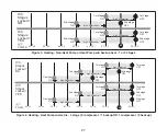
Страница 26: ...rature Humidity offset can be used to offset the displayed room humidity by up to 10 the default offset is 0 Stage Control The following figures list typical configurations H C Stages Locked YES H C Stages Locked NO POINTS 2nd stage ON 2nd stage OFF 1st stage ON 1st stage OFF 2nd stage ON 2nd stage OFF 1st stage ON 1st stage OFF SP 1 5 SP 1 0 SP 0 5 SP SP 1 5 SP 1 0 0 2 P S 5 0 P S Stg1 Differenti...

Страница 27: ...p or Heat Pump w o backup heat 1 or 2 stages H C Stages Locked NO H C Stages Locked YES POINTS 3rd stage ON 1st stage ON 2nd stage ON 3rd stage ON 1st stage ON 2nd stage ON 2nd stage OFF 3rd stage OFF 1st stage OFF 1st stage OFF 2nd stage OFF 3rd stage OFF SP 1 5 SP 1 0 SP 0 5 SP SP 0 5 SP 2 0 Stg1 Differential Stg3 Differential Stg2 Differential SP 2 5 SP 3 0 SP 3 5 Stg1 Differential Stg3 Differe...

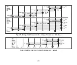
Страница 28: ... SP 1 5 SP 1 0 SP 0 5 SP SP 0 5 SP 2 0 Stg1 Differential Stg3 Differential Stg2 Differential SP 2 5 SP 3 0 SP 3 5 Stg1 Differential Stg3 Differential Stg2 Differential Stg4 Differential Figure 5 Heating Heat Pump w electric 4 stage 2 compressor 2 backup H C Stages Locked NO or YES 2nd stage ON 1st stage ON 2nd stage OFF 1st stage OFF SP 1 5 SP 1 0 SP 0 5 SP SP 0 5 SP 2 0 Stg1 Differential SP 2 5 S...

Страница 29: ... Differential Stg3 Diff Stg2 Differential Figure 7 Heating dual fuel 3 stage 1 compressor 2 backup H C Stages Locked NO H C Stages Locked YES POINTS 3rd stage ON 1st stage ON 2nd stage ON 3rd stage ON 1st stage ON 2nd stage ON 2nd stage OFF 3rd stage OFF 1st stage OFF 1st stage OFF 2nd stage OFF 3rd stage OFF SP 1 5 SP 1 0 SP 0 5 SP SP 0 5 SP 2 0 Stg1 Differential Stg3 Differential Stg2 Differenti...

Страница 30: ...ection Wireless networks supported by this system are 802 11b is 2 4Ghz band max 11 Mbit s 802 11g is 2 4Ghz band max 54 Mbit s 802 11n is 2 4Ghz band max 130 Mbit s This is for connecting the thermostat to a secure home wireless network NOTE A router with Bonjour capabilities is required for this function Check the router functions if the thermostat does not connect Apple Bonjour is an implementa...

Страница 31: ...i screen will appear where you can toggle it to ON Connecting to Visible Home Wi Fi Access Point 1 Touch Wi Fi network This will display a list of visible Wi Fi networks within range of the thermostat 2 Select the homeowner network and type in the password Touch join to continue NOTE The thermostat can connect to a home wireless router that uses up to 32 characters in the access point name visible...

Страница 32: ... to a visible or hidden network if successful a check mark will appear above both the router and Internet icons HOME WI FI ROUTER INTERNET ACCESS SERVER CONNECTION M30 THERMOSTAT Wireless Terminology The following terminology is used Received Signal Strength Indication RSSI This indicates the signal strength of the Wi Fi router being received by the scanning device i e smart phone So the higher th...

Страница 33: ...wireless networks along with button for adding a network 2 Select the access point that has already been established and connected 3 When selecting the info icon a screen will appear which will display an option to forget the network and IP address assigned to the thermostat by your router sub net mask router DNS and RSSI 4 If the RSSI signal strength is anywhere between 9 to 69 then the signal st...

Страница 34: ...ary Typically either after a specific timer period or a specific number of instances some Service Soon alerts will escalate to Service Urgent Service Soon alerts are found only in under the installer alert button Information Only Dealer is information only and helps Lennox interpret test results and understand complicated behaviors Information Only are not reported to homeowner or dealer Communica...

Страница 35: ...emand Heating operation is not allowed Check to ensure that heating equipment is not stuck ON reversing valve etc Check the accuracy of the thermostat temperature sensor Select cooling system mode to cool the indoor space below 90ºF Automatically clears when the system detects that the issue no longer exists 30 Service Urgent Low Temperature Protection The thermostat will not allow any cooling ope...

Страница 36: ...inning of any configuration furnace air handler control or equipment interface module will detect the presence of the sensor s If detected reading in range appropriate feature will be set as installed and shown in the About screen Automatically clears upon configuration or sensing normal values 610 Service Urgent Low Room Temperature Detected This alert will automatically notified the user that a ...

Страница 37: ...a active Wi Fi connection and the user account has been setup and includes a valid email address Automatically clears when condition is resolved 700 Service Urgent Thermostat Temp Sensor Problem The HD display s internal temperature sensor is not operating correctly To resolve this issue try the fol lowing Remove HD display from mag mount and reattaching Seal hole in wall behind mag mount to minim...

Страница 38: ...eset filter reminder for both 3001 Maintenance Replace Filter 2 Not Applicable 3002 Maintenance Replace Humidifier Pad Not Applicable Reset Humidifier pad re minder 3003 Maintenance Replace UV Bulb Not Applicable Reset UV Light reminder 3004 Maintenance Maintenance Reminder Not Applicable Make service appointment with dealer and reset re minder 3005 Maintenance Pure Air Maintenance Not Applicable ...

Страница 39: ... speed Equipment continuous fan speed may not be full cooling air volume Cooing 1st Stage Test will provide a relay output on Y1 for the compressor G for the blower and O Reversing Valves heat pump units If the dehumidification mode option was selected during thermostat setup the thermostat will not provide a 24Vac Output on D during the system test mode and the equipment will operate at the dehum...

Страница 40: ...ns are listed at menu settings humidity Under Humidity Control select dehumidify to enable dehumidification By default it is disabled There are four setting options which are Normal Max Humiditrol and Aux Dehumidifier requires hardware accessory installed Slide bar adjust with a range of 40 to 60 RH Table 10 Dehumidification Modes Option Description Normal Activate If RH measured is RH set point 2...

Страница 41: ...m blower from running at reduced speed if the outdoor temperature is greater than 95 F NOTE The outdoor temperature sensor MUST be attached to the unit in order to use this mode Equipment Operation with Humiditrol Enabled IS THERE A COOLING DEMAND START NO RUN EQUIPMENT IN NORMAL COOLING MODE YES IS THERE A HEATING DEMAND RUN EQUIPMENT IN NORMAL HEATING MODE YES NO IS THERE A DEHUMIDIFICATION DEMA...

Страница 42: ...unit is in Cool mode O ON THEN D is inactive open circuit AND G is ON Deactivate IF RH measured is RH set point 2 or unit isn t in Cool mode B ON THEN D is active G returns to the state determined by the thermostat control either ON Auto or CIRC Humidification Control This option is available if the humidifier accessory is present and enabled in the Advanced Settings System Setup Under Advanced Se...

Страница 43: ...t mode O ON then H is Off G returns to the state determined by the thermostat control either ON Auto or CIRC NOTE The D terminal is active during humidification Following is the table that shows status of FAN for different humidity modes and system outputs Normal and Max Dew Point Control To set the system to Normal Dew Point Control select normal and dew point options under settings humidity opti...

Страница 44: ...re known Once the thermostat s CFMs are adjusted they are used with the thermostat s timer algorithm to determine how long to run the HRV ERV Energy Recovery Ventilator ERV The ERV unit is equipped with an enthalpic core This device is designed for use in warm humid climates with heavy air conditioning loads The ERV unit transfers both sensible temperature and latent moisture heat from incoming fr...

Страница 45: ... override Operation is otherwise the same as the ASHRAE compliant method Terminals ACC1 and ACC2 are dry contacts in this mode Ventilation Wiring ACC 1 ACC 2 Wire Jumper required between ON and RED terminals LOW ON RED YEL GRN HI COM NO NC BLK HRV ERV Terminal Block M30 Low Speed Remove the factory installed jumper between ACC1 and R2 terminals The on board 24VAC power source cannot be used R2 For...

Страница 46: ...tilation Control Modes Parameter settings and descriptions are listed in Table 5 Advanced Settings on page 14 The table below list which parameters are available for the Fresh Air Damper ERV and HRV equipment ...

Страница 47: ...erature display setting is configured for sensor If OATS is not used leave the setting on Internet 4 Have all the Thermostat Features been explained to the Home Owner 5 Has User manual been given to Home Owner 6 Has additional Alexa information not in user manual been given to Home Owner and shown where to find answers to additional questions Go to www myicomfort com Support page FAQ 7 Is the Wi F...

Страница 48: ...ble has the air handler s electric heat strips been commissioned If not commissioning of heat strips must be performed 12 Has a complete system test been run If not from the HD Display home screen go to settings advanced settings view dealer control center and select tests ...

Страница 49: ...49 ...

Страница 50: ...50 ...

Страница 51: ...51 ...

Страница 52: ...int 25 N New Installation 5 O Offset 22 26 Outdoor Air Temperature Sensor OATS 4 Outdoor Sensor 16 P Parameter Descriptions 22 R Received Signal Strength Indication RSSI 33 Replacement Installation 6 Reset Settings 21 Residual Cooling 16 Restart Thermostat 21 S Smart Away 25 Smooth Setback Recovery 18 22 Stage 2 Heat Pump Lock Temp 21 Stage 2HP Lock Temp 25 Stage Control 26 Stage Delays 18 24 Stag...

Отзывы: