


7. 3D ASSIST DISPLAY FEATURE (OPTION)
65
7.9.1
Selecting the Display Format
To select the video signal waveform display format, follow the procedure below.
Procedure
MULTI
→
F•5 WFM SETUP
→
F•1 WFM FORM
Settings
ALIGN:
Channel A (the video signal for the left eye) and channel B (the video signal
for the right eye) are displayed side by side (this is the default value).
MIX:
Channel A (the video signal for the left eye) and channel B (the video signal
for the right eye) are displayed on top of each other. When F•2 WFM COLOR
is set to RED,CYAN, only the parts where disparity exists are colored.
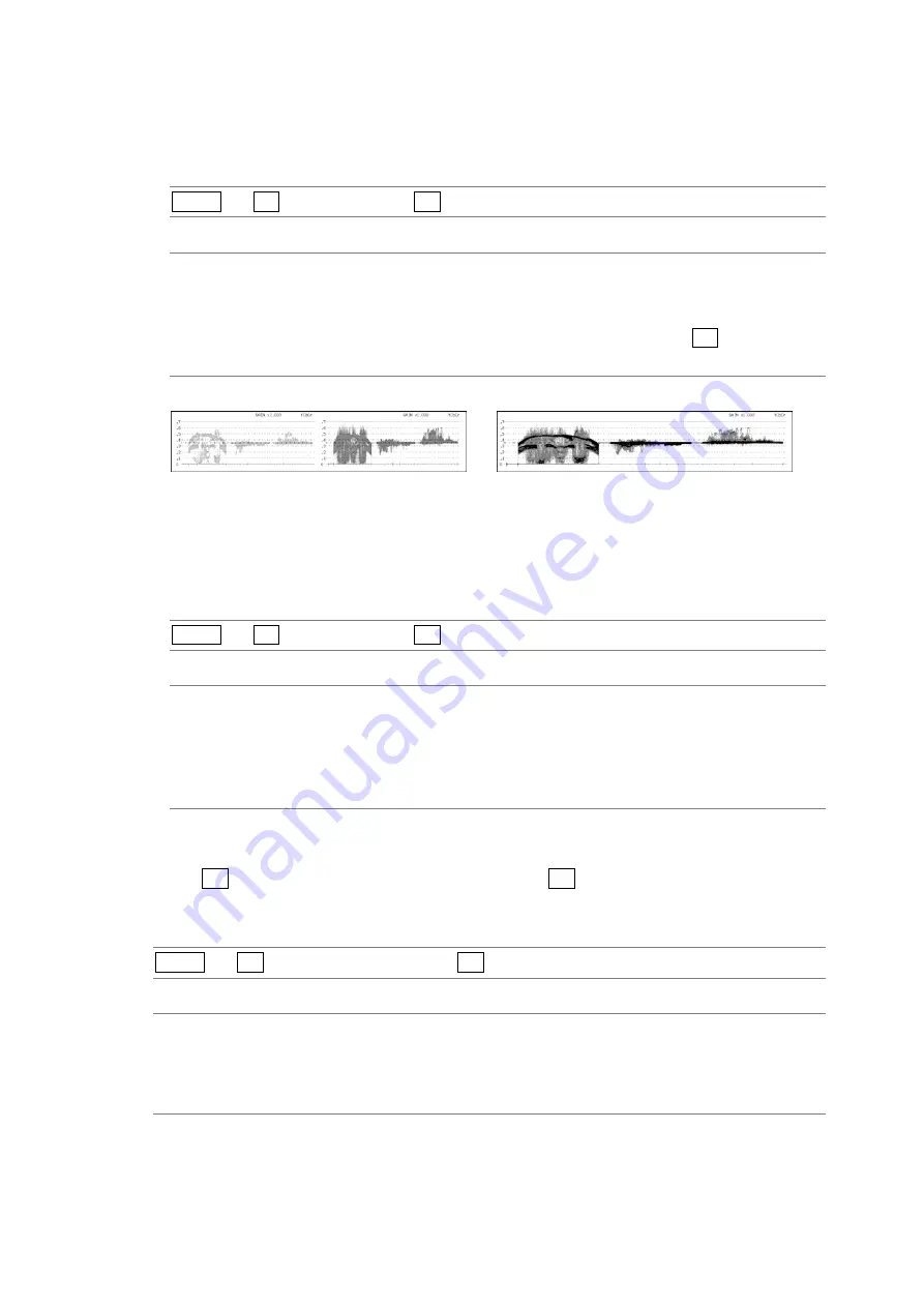
WFM FORM = ALIGN
WFM FORM = MIX
Figure 7-9 Selecting the display format
7.9.2
Selecting the Video Signal Waveform Color
To select the video signal waveform color, follow the procedure below.
Procedure
MULTI
→
F•5 WFM SETUP
→
F•2 WFM COLOR
Settings
RED,CYAN: Channel A (the video signal for the left eye) is displayed in red, and channel B
(the video signal for the right eye) is displayed in cyan (this is the default
value).
SINGLE:
Waveforms are displayed in the color specified by WFM COLOR on the video
signal waveform menu.
7.10
Setting the Histogram
When F•7 3D INPUT FORMAT is set to L/R DUAL and F•4 SUB-ITEM is set to HISTOGRAM,
to select the histogram display channel, follow the procedure below.
Procedure
MULTI
→
F•5 HISTOGRAM SETUP
→
F•2 L/R SELECT
Settings
LEFT:
Channel A (the video signal for the left eye) is displayed.
RIGHT:
Channel B (the video signal for the right eye) is displayed.
L&R:
Channel A (the video signal for the left eye) and channel B (the video signal for
the right eye) are displayed on top of each other (this is the default value).


