


7. 3D ASSIST DISPLAY FEATURE (OPTION)
58
7.6
Selecting the Measurement Mode
When F•1 PICTURE FORM is set to AGLPH CL, AGLPH MO, CNVRGNCE, or OVERLAY,
you can use the grid or the cursors to measure disparity.
To select the disparity measurement mode, follow the procedure below.
Procedure
MULTI
→
F•2 3D FUNCTION
→
F•3 MEASURE SELECT
Settings
OFF:
No grid lines or cursors are displayed (this is the default value).
GRID:
Grid lines are displayed. You can use the grid to measure disparity.
DISPRTY:
Cursors are displayed. You can perform detailed disparity measurements by
setting the viewing environment.
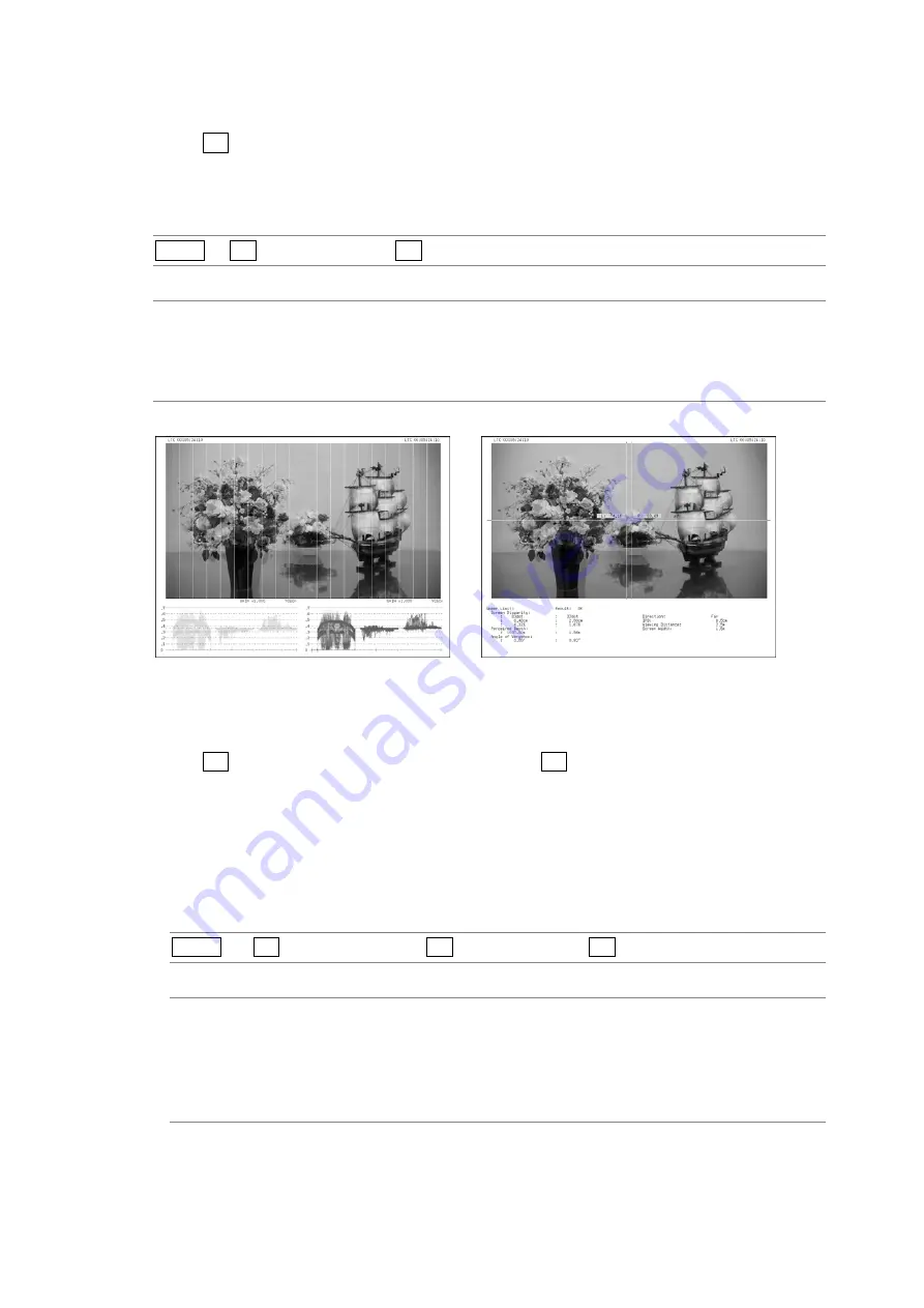
MEASURE SELECT = GRID
MEASURE SELECT = DISPRTY
Figure 7-3 Selecting the measurement mode
7.7
Configuring Grid Display Settings
When F•3 MEASURE SELECT is set to GRID, press F•4 GRID SETUP to configure the grid
settings.
7.7.1
Selecting the Displayed Grid
To select the type of grid that is displayed, follow the procedure below. The reference grid
lines for both the disparity and horizontal grid lines are displayed in yellow.
Procedure
MULTI
→
F•2 3D FUNCTION
→
F•4 GRID SETUP
→
F•1 GRID DISPLAY
Settings
DISPRTY:
Vertical grid lines are displayed. Use this option when you want to perform
disparity measurements (this is the default value).
HORIZONT: Horizontal grid lines are displayed. Use this option when you want to match
the horizontal position of one camera or multiple cameras.
BOTH:
Both vertical and horizontal grid lines are displayed.


