


C
REATING
C
USTOM
C
OMPONENTS
IN
L
ATTICE
M
ICO
S
YSTEM
:
Specifying RTL Files
LatticeMico32 Hardware Developer User Guide
73
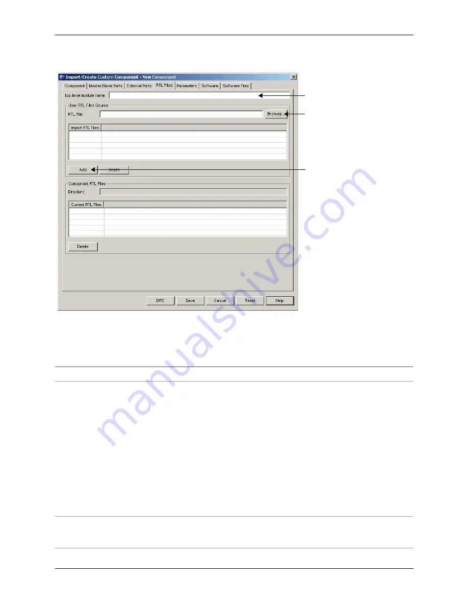
Table 6 lists the options available in the RTL Files tab of the Import/Create
Custom Component dialog box.
Figure 39: Specifying the RTL Files
Step1: Specify top-level module
name of your custom component.
Step 2: Select RTL file.
Step 3: Click
Add
button.
Table 6: RTL Files Tab Options
Option
Description
Top-Level Module Name
If the custom component is a Verilog component, this option specifies the top-
level module name of the custom component.
If the custom component is a VHDL component, you must create a Verilog black-
box definition of the VHDL custom component and specify the name of the
Verilog black-box module.
The GUI creates a wrapper that instantiates the top-level module of the Verilog
custom component or the Verilog black-box module for a VHDL custom
component according to the port specifications for the custom component
provided in the Master/Slave Ports and External Ports tabs and the parameters
specification provided in the Parameters tab.
For VHDL custom components, passing VHDL generics is not supported, since
the VHDL custom component flow relies on .ngo files. Refer to “Creating the
Verilog Wrapper for VHDL Designs” on page 87 for more information on
importing VHDL WISHBONE-compliant custom components.
RTL File
This entry box enables you to enter a file name containing HDL code that is a
part of your component. Enter a
path and module name directly or use the
Browse button to add HDL files interactively.


