


C
REATING
C
USTOM
C
OMPONENTS
IN
L
ATTICE
M
ICO
S
YSTEM
:
Custom Component Example
112
LatticeMico32 Hardware Developer User Guide
Output
After you perform the steps in the “Adding the Custom Component” on
page 100, the component now appears in the MSB graphical user interface,
as shown in Figure 68.
When you double-click on this component, a configuration dialog box opens,
as shown in Figure 69, so that you can configure it when instantiating it in a
platform.
Figure 70 shows the directory structure and the contents of the directories
created by the MSB graphical user interface.
The directory structure shown in Figure 70 is created automatically by the
Import/Create Custom Component dialog box. The source files are copied
from the source folder into the directory structure. If you want to modify the
RTL once this component is created—for example, to fix a bug—you must
modify the copied files, not the original source files.
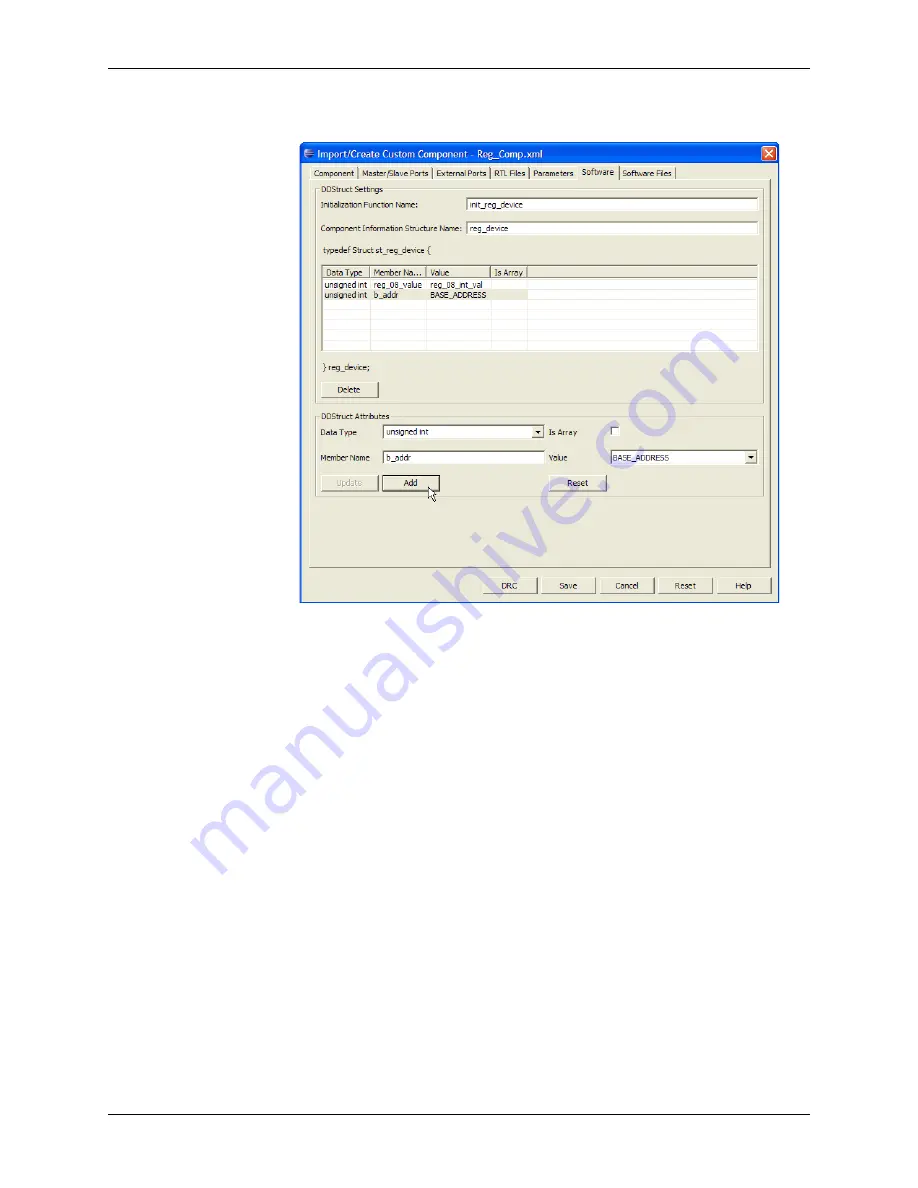
Figure 65: Specifying Second Data Structure


