


UNDERSTANDING THE BENDI B40I4 FORKLIFT
3-7
Mast Tilt
he mast tilt circuit provides the means for tilting the mast
and fork assembly forward and back. Tilting movements
are accomplished through the use of two hydraulic
double-acting cylinders mounted to the top of the front
plate.
Mast Side Shift
The side shift circuit provides the means for moving the
carriage laterally (left-to-right). Side shift movements are
accomplished using a double acting hydraulic cylinder
that pushes the carriage side to side, mounted on
nylatron slides.
Mast Lift Assemblies
Various mast assembly configurations (triplex or quad)
can be applied to the B40i4 Model trucks to provide both
collapsed and extended heights suitable for all customer
requirements. The lifting capacity of the mast also varies
depending on the truck and its application. Load
capacities are determined at 24” (609.6 mm) centers,
centered on the mast and include all attachments on the
carriage. The B40i4 specifications list the dimensions of
standard masts available for these trucks. See “Technical
Specifications” on page 5-9.
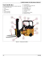
Also check the identification plate in the operator’s
compartment for the maximum lifting capabilities, based
on the particular truck and mast combination. See
Figure 3-2.
The trucks are counterweighted to compensate for all
positions up to the maximum allowed load.
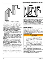
Masts are engineered to distribute thrust loads evenly
between the rollers and rails. Masts move as a unit,
providing maximum strength and endurance for the rated
load and consist of up to four pairs of channels or rails
(steel beams) rolling one within the other on steel rollers.
The outer rails provide guidance and support for the
middle rails, which in turn guide and support the inner
rails. The truck forks are mounted on a carriage assembly
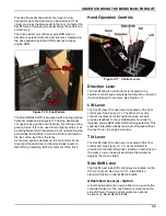
that runs on rollers within the inner rails. See Figure 3-6.
Figure 3-6: Mast in Collapsed Position
On a triplex mast, a primary cylinder is supported by the
inner rails and hydraulically controlled. As the primary
cylinder rod extends, a sheave and chain assembly lift
the fork/carriage upward at twice the distance covered by
the cylinder rod. This first stage of carriage lift is called
free lift. It is the distance of lift available without
increasing the overall height of the mast assembly. See
Figure 3-7.
Figure 3-7: Mast in Free Lift Position
A secondary cylinder, attached to the outer rails, lifts the
middle and inner rails progressively via chains, rollers
and sheaves. The inner rails are raised at twice the rate
of extension of the secondary cylinder piston. This
upward lift continues until the secondary cylinders are
fully extended. See Figure 3-8.
Содержание Bendi B40i4
Страница 2: ......
Страница 12: ...1 4 F 808 R0 FORKLIFT SAFETY AND FAMILIARITY Figure 1 2 Decals...
Страница 18: ...1 10 F 808 R0 FORKLIFT SAFETY AND FAMILIARITY Table provided for general use NOTES...
Страница 24: ...2 6 F 808 R0 RECEIVING AND INSPECTION Table provided for general use NOTES...
Страница 54: ...4 16 F 808 R0 OPERATING THE B40I4 FORKLIFT Table provided for general use NOTES...
Страница 62: ...5 8 F 808 R0 Figure 5 5 Lubrication Points...
Страница 64: ...5 10 F 808 R0 Table provided for general use NOTES...


