3-8
F-808-R0
UNDERSTANDING THE BENDI B40I4 FORKLIFT
Figure 3-8: Mast Fully Extended
The hydraulic fluid used to lift the primary cylinder is
applied sequentially to the secondary cylinder. When the
primary cylinder reaches full extension, the secondary
cylinder begins to extend. The differences in weights
being supported by the cylinders, along with the
differences in cylinder diameters, ensure that the primary
cylinder will be fully extended before the secondary
cylinder can begin to move. Consequently, when the
mast is raised, it moves through two phases:
• Free lift, in which only the carriage assembly moves,
up to the maximum height allowed by the inner rail.
See Figure 3-6.
• Rail extension, in which both the middle and inner rail
moves, carrying the carriage upward. See Figure 3-7.
Downward movement of the mast is accomplished by
releasing the hydraulic fluid from the cylinders back into
the reservoir.
The weight of the rails and carriage(& load) provides
enough pressure to force the fluid from the cylinders.
When the secondary cylinder piston is fully contracted,
the primary cylinder begins to collapse, forcing its fluid
back to the reservoir.
The mast is supported by trunnions, which allow it to tilt
fore and aft. Two short hydraulic cylinders are mounted
between the mast and the pivot arm to control the
amount of tilt. A mast indicator gauge (pointer) is located
on the both sides of the mast to indicate when the
carriage and forks are perfectly level with the floor.
As an option, trucks may be equipped with quad masts
which utilize four sets of rails, referred to as Outer, Outer
Intermediate, Middle, and Inner rails, respectively. See
Figure 3-9.
Figure 3-9: Quadplex Mast in Collapsed Position
The primary cylinder and carriage operate the same as a
triplex (three-rail) mast. When the secondary cylinders
extend, they lift the middle rails. Through an intricate
system of chains and sheaves, the rising middle rails pull
up the outer intermediate rails at half the middle rail
speed, and push up the inner rails at twice the middle rail
speed.
Driver Controls
Driving controls for the Bendi B40i4 truck include a stop
pedal and a drive foot pedal for speed control,
tilting/telescoping steering wheel, Keyswitch, dash
display, forward and reverse direction control lever, tilt/lift
and side shift controls, horn button, rear view mirror and
drivers seat adjustments.
WARNING
Foot Control Pedals
The foot pedals consists of a drive pedal and a stop
pedal. The drive pedal is pressed by the driver’s right foot
to control the speed of the truck.
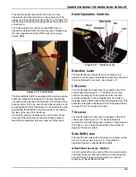
The drive pedal is the pedal on the right, and the stop
brake is the pedal on the left. See Figure 3-10.
3
• Driving speed of the truck must be governed
by your work environment, such as, slippery
floors, cross aisles, slanted driving surfaces,
load size, visibility or other people working in
the area.
• Never travel at speeds with or without a load
that could be dangerous to yourself or others.
Also see the Safety section in the beginning
of this manual, Chapter 1, HEAD AND PAGE.
Содержание Bendi B40i4
Страница 2: ......
Страница 12: ...1 4 F 808 R0 FORKLIFT SAFETY AND FAMILIARITY Figure 1 2 Decals...
Страница 18: ...1 10 F 808 R0 FORKLIFT SAFETY AND FAMILIARITY Table provided for general use NOTES...
Страница 24: ...2 6 F 808 R0 RECEIVING AND INSPECTION Table provided for general use NOTES...
Страница 54: ...4 16 F 808 R0 OPERATING THE B40I4 FORKLIFT Table provided for general use NOTES...
Страница 62: ...5 8 F 808 R0 Figure 5 5 Lubrication Points...
Страница 64: ...5 10 F 808 R0 Table provided for general use NOTES...


