8
1
General Information
1.2
How to Use These Instructions
1.2.1
Purpose
This manual consists of all necessary information for its designated use.
Additional information such as configuration examples, application possibilities, software set-
tings, etc can be found in separate publications.
Special information which involves optional components for this device are described in a sep-
arate print.
1.2.2
Conventions
1.2.3
Correcting Faults
Information regarding localisation of errors and its remedies as well as a list of fault codes,
fault text and help can be found in chapter
8.1.4 Proceed with Programming
This chapter, makes no claim as to the completeness of the information. If the actions de-
scribed do not lead to the desired result, the unit or parts of the unit (e.g. front panel etc.) must
be changed. If the fault still occurs, it is probably a plant-specific fault.
NOTICE
You can download the up-to-date version of these instructions from http://www.lamtec.de
as a PDF File.
You will find the version number at the backside of this document:
For example:
DLT 1015-08-aEN-017
DLT 1015 = document number
aEN = print version and language (EN for English)
017 = version number
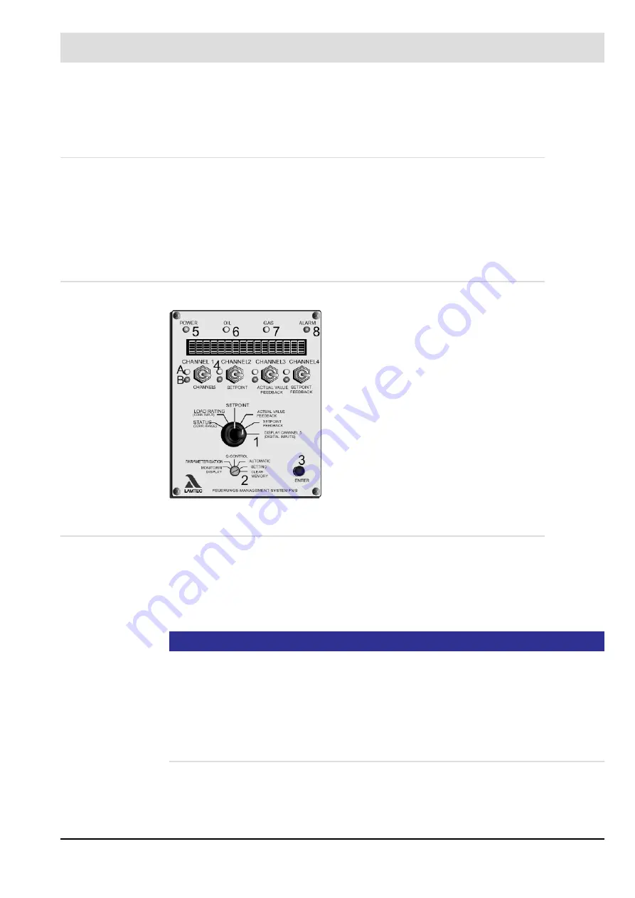
The figures and letters in brackets (1), (2), (3), (4), (5),
(6), (7), (8), (A) and (B) relate directly to the picture of
the front panel. They identify the part on which the spec-
ified action is to be performed or on which a reaction
can be seen.
The lines below the procedural instruction describe the
reaction of the system or unit following the operation.
If you now follow the operations step by step, paying
attention to the instructions, you will automatically be
working correctly. If any of the operations indicated do
not occur, there is a fault with the unit or the system.
You should correct the fault first before proceeding.
Содержание VMS 4
Страница 1: ...www lamtec de Sensors and Systems for Combustion Technology Manual Fuel Air Ratio Control System VMS...
Страница 2: ......
Страница 119: ...118 10 Appendix...
Страница 121: ...120 10 Appendix 10 6 Process Sequence Charts Fig 10 3 Sequence of functions VMS digital inputs sequencer...
Страница 129: ...128 10 Appendix Fig 10 9 Ger t 4 Ger t 5 with output regulator...
Страница 141: ...140 10 Appendix 10 14 Declaration of Conformity...
Страница 142: ...141 10 Appendix...
Страница 143: ...142 10 Appendix 10 15 Protocol Example...
Страница 144: ...143 10 Appendix 10 16 O2 Setpoint Curves...
Страница 145: ...144 10 Appendix...


