


43
4
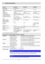
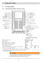
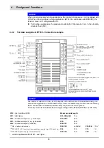
Design and Functions
NOTICE
For continuous operation, connect following types of flame sensors to BurnerTronic BT330
and BT340:
Flame scanners with ionisation electrode
Flame monitor for continuous operation with potential-free contact e.g. F200K.
The fastening system must be designed in a way that unintentional detachment of the
flame monitor is prevented.
Up to version 3.8.0.0, the BT320 is only approved for intermittent operation with these flame
scanners. From serial number 22xxxxxx and version 3.9.0.0, the BT320 is also approved for
continuous operation.
WARNING!
Danger from fuel ingress to combustion chamber after loss of flame!
Improper use or configuration of flame sensors not approved for continuous operation can re-
sult in hazardous situations and possible cause of explosion leading to loss of life and prop-
erty. Failure to detect the loss of flame may result in an ingress of fuel into the combustion
chamber and subsequent explosive condition.
Make sure during setting of P300 to the approval of the scanner.
Only set P300 to the value 0 if the flame sensor and the BT300 is approved for continuous
operation.
NOTICE
The flame sensor QRA53 …, 55 …, 73 … and 75 are
not
authorized together with BT300 for
continuous operation. The test of the UV tube via shutter is
not
supported by BT300.
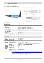
4.3.2
Flame Sensors
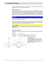
4.3.2.1 KLC 20/KLC 2002
Brief Description
The wide band flame detector KLC 20/KLC 2002 is a compact flame detector, which is special
designed for blue burning combustion systems. The patented flame signal evaluation is based
on the flicker frequencies of the flame. A RISC-Processor enables evaluation and conversion
of the flame signal into digital information to provide an output signal for burner control boxes.
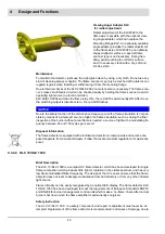
All flames will be detected by an automatic sensitivity control. Adjustments during commis-
sioning and maintenance are not necessary!
Per international standards, the KLC 20/KLC 2002 will only detect signals caused by the flame
flicker. Signals from continuous radiation and any kinds of constant frequency will be ignored.
Signals caused by disturbing light sources, such as fluorescent tubes or background radiation
from hot refractory will be cut off, so that unwanted influences are not possible.
By using LED-Display as an optical interface, the flame detector is able to read different rele-
vant operating parameters (e.g. monitoring of flame signals, serial number).
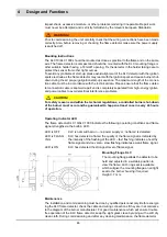
Safety Instructions
The KLC 20/KLC 2002 is a safety device. Do not open, modify, or misuse it! Replace the flame
detector in case of any damage, if dropped, exposure to shock, moisture, excessive temper-
ature, or conditions that can destroy the flame detector, even though damage is not obvious.
Repair is strictly prohibited!
Содержание BT300 BurnerTronic
Страница 2: ......
Страница 21: ...20 3 Product Description Fig 3 3 UI300 and Fig 3 4 UI300 and dimensional drawings Fig 3 5 UI300 panel cut out...
Страница 25: ...24 3 Product Description Fig 3 9 Temperature derating BT300 for operation 2000 m NHN...
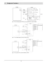
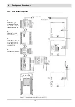
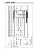
Страница 49: ...48 4 Design and Functions Fig 4 20 Oil with pilot burner BT300...
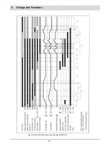
Страница 50: ...49 4 Design and Functions Fig 4 21 Oil without pilot burner BT300...
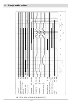
Страница 51: ...50 4 Design and Functions Fig 4 22 Gas with pilot burner and leakage test BT300...
Страница 52: ...51 4 Design and Functions Fig 4 23 Gas without pilot burner and leakage test BT300...
Страница 53: ...52 4 Design and Functions Fig 4 24 Oil without pilot burner BT335...
Страница 54: ...53 4 Design and Functions Fig 4 25 Gas without pilot burner and leakage test BT335...
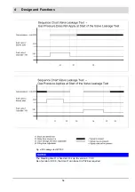
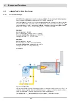
Страница 59: ...58 4 Design and Functions Fig 4 28 Leakage test process diagram...
Страница 98: ...97 6 Operating Control and Displays...
Страница 99: ...98 6 Operating Control and Displays...
Страница 102: ...101 6 Operating Control and Displays NOTICE If the license agreements are not accepted the installation is aborted...
Страница 103: ...102 6 Operating Control and Displays...
Страница 105: ...104 6 Operating Control and Displays...
Страница 106: ...105 6 Operating Control and Displays...
Страница 107: ...106 6 Operating Control and Displays...
Страница 109: ...108 6 Operating Control and Displays...
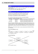
Страница 126: ...125 6 Operating Control and Displays 6 3 4 2 Curve Table Fig 6 37 Curve table window...
Страница 246: ...242 10 EU Declaration of Conformity 10 EU Declaration of Conformity...
Страница 247: ...243 10 EU Declaration of Conformity...
Страница 248: ...244 10 EU Declaration of Conformity...


