


216
8
Options
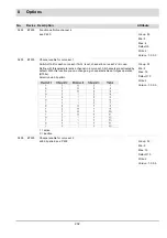
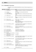
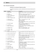
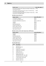
Tab. 8-1 specification of client input data
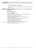
The assignment of Packet Data Units of Input data, transferred via PBM from PROFIBUS to
LSB:
52 - 53
Status of efficiency
Bit pattern corresponding to
, table ’Bit Pattern Status of
Flue Gas Temperature and Efficiency’
54 - 55
Flame intensity
0 to 100 in steps of 1 %
56 - 57
Actual value monitoring output
16 bit Integer
58 - 59
Burner control state
Bit pattern corresponding to
, table ’Bit Pattern FAT Sta-
tus’
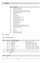
Byte position
Description
Note
Byte position
Description
0 - 1
Burner ON (byte 1, bit 0, 1: ON),
Fuel pre-selection (byte 1, bit 1, 1: oil, 0: gas), Fault reset (byte 1, bit 2)
2 - 3
Pre-setting burner firing rate, 0 ... 999,
Validation bit 15 = 1 (Byte 2, 3 = b1XXXXXXX XXXXXXXX):
Sets priority for burner firing rate pre-setting by PROFIBUS
4 - 5
pre-setting status of burner firing rate (actually not in use)
6 - 7
Pre-setting setpoint of burner firing rate controller,
0 ... 999, values correspond to the indication of actual value and setpoint value
8 - 9
Status of burner firing rate controller’s setpoint,
Validation bit 15 = 1 (Byte 8, 9 = b1XXXXXXX XXXXXXXX):
Evaluation of setpoint value by LCM
10 - 11
Smooth setpoint shift of firing rate controller, int16,
value range is defined by upper and lower limits.
12 - 13
Status of smooth setpoint shift of burner firing rate controller
Validation bit 15 = 1 (Byte 12, 13 = b1XXXXXXX XXXXXXXX):
sets analysis of setpoint shift by LCM
Содержание BT300 BurnerTronic
Страница 2: ......
Страница 21: ...20 3 Product Description Fig 3 3 UI300 and Fig 3 4 UI300 and dimensional drawings Fig 3 5 UI300 panel cut out...
Страница 25: ...24 3 Product Description Fig 3 9 Temperature derating BT300 for operation 2000 m NHN...
Страница 49: ...48 4 Design and Functions Fig 4 20 Oil with pilot burner BT300...
Страница 50: ...49 4 Design and Functions Fig 4 21 Oil without pilot burner BT300...
Страница 51: ...50 4 Design and Functions Fig 4 22 Gas with pilot burner and leakage test BT300...
Страница 52: ...51 4 Design and Functions Fig 4 23 Gas without pilot burner and leakage test BT300...
Страница 53: ...52 4 Design and Functions Fig 4 24 Oil without pilot burner BT335...
Страница 54: ...53 4 Design and Functions Fig 4 25 Gas without pilot burner and leakage test BT335...
Страница 59: ...58 4 Design and Functions Fig 4 28 Leakage test process diagram...
Страница 98: ...97 6 Operating Control and Displays...
Страница 99: ...98 6 Operating Control and Displays...
Страница 102: ...101 6 Operating Control and Displays NOTICE If the license agreements are not accepted the installation is aborted...
Страница 103: ...102 6 Operating Control and Displays...
Страница 105: ...104 6 Operating Control and Displays...
Страница 106: ...105 6 Operating Control and Displays...
Страница 107: ...106 6 Operating Control and Displays...
Страница 109: ...108 6 Operating Control and Displays...
Страница 126: ...125 6 Operating Control and Displays 6 3 4 2 Curve Table Fig 6 37 Curve table window...
Страница 246: ...242 10 EU Declaration of Conformity 10 EU Declaration of Conformity...
Страница 247: ...243 10 EU Declaration of Conformity...
Страница 248: ...244 10 EU Declaration of Conformity...


