


219
8
Options
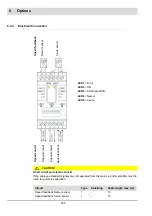
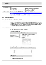
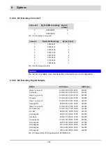
8.5.2.2 DIP Switch
All settings of the device are configured by means of DIP switches.
Tab. 8-2 Function of the DIP switches
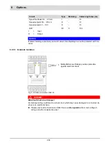
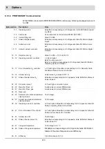
8.5.2.3 LEDs
EBM100 has 4 LED and 2 additional LED at the RJ45 socket, which should be connected as
described below:
Tab. 8-3 LED signalling
DIP switch no.
Settings
1 - 2
1 2
0 0
0 1
1 0
1 1
LSB Family
1
2
3
4
3
CAN terminal resistance
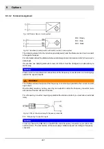
LED
Colour
Description
PWR
green
ON:
Module working in normal mode = fully initialised and
without any fault.
CAN
green
OFF:
No communication or CAN BUS error
Flashing with 2 Hz:
Sporadic errors (optional, if a CAN
warning is detectable).
ON:
CAN is functioning.
ETH
green
OFF:
No communication on Ethernet
Flushing with 2 Hz:
Ethernet – Fieldbus is initialised. Mas-
ter/Client not connected
ON:
Master/Client is connected. Communication by Ether-
net is failure free.
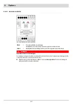
ERR
red
OFF:
No error.
Flashing with 2 Hz:
– No CAN message for more than 3 s.
– IP configuration does not correspond with the specifica-
tions in the BT parameter.
ON:
EBM100 not ready.
ACT
yellow
OFF:
No Ethernet activity
Flashing:
Module is sending/receiving Ethernet frames
LINK
green
OFF:
Ethernet connection is active
Flashing:
– no connection to Ethernet
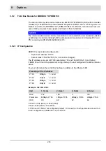
ERR
ETH
CAN
PWR
Condition
OFF
ON
ON
ON
Device started, no error:
– CAN bus OK,
– CAN communication OK,
– Fieldbus master connected
OFF
Flashing
X
1
ON
– Device started
– Fieldbus master not connected
Содержание BT300 BurnerTronic
Страница 2: ......
Страница 21: ...20 3 Product Description Fig 3 3 UI300 and Fig 3 4 UI300 and dimensional drawings Fig 3 5 UI300 panel cut out...
Страница 25: ...24 3 Product Description Fig 3 9 Temperature derating BT300 for operation 2000 m NHN...
Страница 49: ...48 4 Design and Functions Fig 4 20 Oil with pilot burner BT300...
Страница 50: ...49 4 Design and Functions Fig 4 21 Oil without pilot burner BT300...
Страница 51: ...50 4 Design and Functions Fig 4 22 Gas with pilot burner and leakage test BT300...
Страница 52: ...51 4 Design and Functions Fig 4 23 Gas without pilot burner and leakage test BT300...
Страница 53: ...52 4 Design and Functions Fig 4 24 Oil without pilot burner BT335...
Страница 54: ...53 4 Design and Functions Fig 4 25 Gas without pilot burner and leakage test BT335...
Страница 59: ...58 4 Design and Functions Fig 4 28 Leakage test process diagram...
Страница 98: ...97 6 Operating Control and Displays...
Страница 99: ...98 6 Operating Control and Displays...
Страница 102: ...101 6 Operating Control and Displays NOTICE If the license agreements are not accepted the installation is aborted...
Страница 103: ...102 6 Operating Control and Displays...
Страница 105: ...104 6 Operating Control and Displays...
Страница 106: ...105 6 Operating Control and Displays...
Страница 107: ...106 6 Operating Control and Displays...
Страница 109: ...108 6 Operating Control and Displays...
Страница 126: ...125 6 Operating Control and Displays 6 3 4 2 Curve Table Fig 6 37 Curve table window...
Страница 246: ...242 10 EU Declaration of Conformity 10 EU Declaration of Conformity...
Страница 247: ...243 10 EU Declaration of Conformity...
Страница 248: ...244 10 EU Declaration of Conformity...


