


170
8
Options
8.1.7
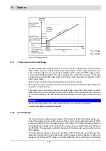
Thermostat and Control Range
The thermostat function switches burner on and off on basis of temperature and/or pressure
value. At first, the burner must be released by starting signal. Control range is formed by en-
tering controller setpoint value, parameters P 0054 (switch-on point), P 0055 (upper control
range) and P 0056 (burner OFF). The shut-off hysteresis is divided into 2 ranges. The first part
is located above setpoint forms the upper control range. Second part below setpoint forms the
lower control range.
Control range is possibly located asymmetrically around the setpoint.
Below upper control range power control unit functions work according to settings made in pa-
rameters and default values.
If the control units’ actual value reaches shut-down range a base firing rate request is emitted.
While setpoint of control units exceeds shut-down range a control shut-off occurs. This done
by internal processing. If the actual value drops below lower control range, a re-start can hap-
pen.
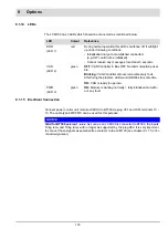
NOTICE
This function may replace the control thermostat, which is required on the plant.
It does not replace a safety thermostat.
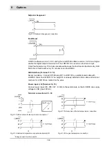
8.1.8
Control Range
The control range is located around setpoint. The content of ’burner ON’ parameter is sub-
tracted from setpoint to form switch-on value. ’Upper control range’ parameter value (P 0055)
is added to setpoint to form the upper limit of control range. The control range may therefore
be located asymmetrically around setpoint.The shut-off range is limited by ’Burner off’ param-
eter (P 0056). The parameter is added to the setpoint. If this value is exceeded a burner shut-
off is initiated.
The range between ’Upper control range’ and ’Burner OFF’ is forming the shut-off range. If the
actual value reaches this range fuel/air ratio control changes to base firing rate. Another con-
sequence is that ’Burner OFF’ value is in general higher than the one of ’Upper control range’
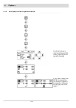
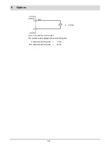
Fig. 8-4 Start-up sequence
*(1) = P 0044
*(2) = P 0045
Содержание BT300 BurnerTronic
Страница 2: ......
Страница 21: ...20 3 Product Description Fig 3 3 UI300 and Fig 3 4 UI300 and dimensional drawings Fig 3 5 UI300 panel cut out...
Страница 25: ...24 3 Product Description Fig 3 9 Temperature derating BT300 for operation 2000 m NHN...
Страница 49: ...48 4 Design and Functions Fig 4 20 Oil with pilot burner BT300...
Страница 50: ...49 4 Design and Functions Fig 4 21 Oil without pilot burner BT300...
Страница 51: ...50 4 Design and Functions Fig 4 22 Gas with pilot burner and leakage test BT300...
Страница 52: ...51 4 Design and Functions Fig 4 23 Gas without pilot burner and leakage test BT300...
Страница 53: ...52 4 Design and Functions Fig 4 24 Oil without pilot burner BT335...
Страница 54: ...53 4 Design and Functions Fig 4 25 Gas without pilot burner and leakage test BT335...
Страница 59: ...58 4 Design and Functions Fig 4 28 Leakage test process diagram...
Страница 98: ...97 6 Operating Control and Displays...
Страница 99: ...98 6 Operating Control and Displays...
Страница 102: ...101 6 Operating Control and Displays NOTICE If the license agreements are not accepted the installation is aborted...
Страница 103: ...102 6 Operating Control and Displays...
Страница 105: ...104 6 Operating Control and Displays...
Страница 106: ...105 6 Operating Control and Displays...
Страница 107: ...106 6 Operating Control and Displays...
Страница 109: ...108 6 Operating Control and Displays...
Страница 126: ...125 6 Operating Control and Displays 6 3 4 2 Curve Table Fig 6 37 Curve table window...
Страница 246: ...242 10 EU Declaration of Conformity 10 EU Declaration of Conformity...
Страница 247: ...243 10 EU Declaration of Conformity...
Страница 248: ...244 10 EU Declaration of Conformity...


