Page 59
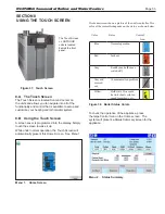
The Configuration Sub-Menus (
ALL
18 )
8.G.
1 __ 18
Some of these configurations will require a Login first.
See Menu 3 on page 54
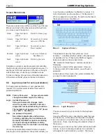
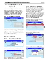
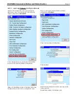
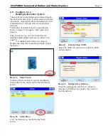
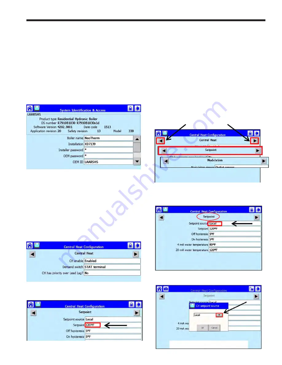
The Central Heat Configuration Menu ( ) has three
sub-menus and each of them can be reached by
scrolling left or right thru the arrows on the left and
right. See Menu 18. The three sub-menus are
‘Central Heat’, ‘Setpoint’, and ‘Modulation’.
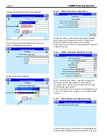
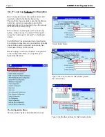
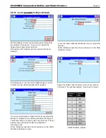
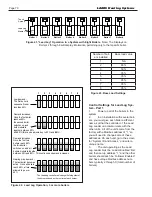
To set up 4-20 mA Setpoint, you will need to go into
the ‘Setpoint’ sub-menu first and change the Setpoint
source from Local to S2 (J8-6) 4-20 mA. Then go to
the ‘Modulation’ sub-menu and set the Modulation
source to Local. Both Setpoint and Modulation
cannot have their source set as Local.
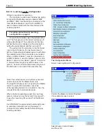
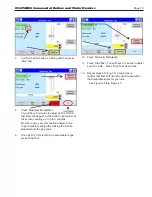
From the Central Heat Configuration Sub-Menu,
choose either the left or right arrow.
then Click onto ‘Local’.
When using the unit for hydronic heating, a call for
heat must be supplied to the “T-T” terminals found on
TB7 labeled “T-T or Interlock”. Once a call for heat
is established, the control will start the appropriate
(selected) pumps, and begin the ignition process.
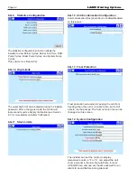
8.G.1
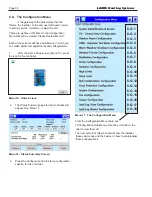
System Identification & Access
This sub-menu will display information regarding software,
date codes, model numbers and program name, as well
as giving the installer access to re-name the boiler and
to change the modbus addresses for lead lag operation.
Press the back arrow on the top right corner of the screen
to return to the ‘Configuration Menu’.
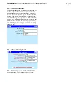
8.G.2
Heat Configuration
8.G.2.a
CH - Central Heat Configuration
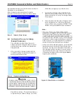
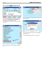
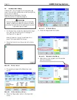
Make sure that CH is Enabled and then press one of the
black arrows (either side) to get to the Set-Point screen.
Press on the ‘Setpoint’ box to make adjustments to
setpoint, and modulation for a single boiler CH demand.
until you are on the ‘Setpoint’ sub-menu,
Menu 18.
The Setpoint submenu
8.G.2.b
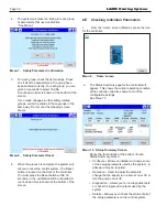
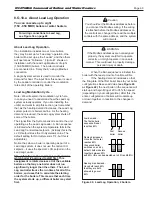
Setting Up 4-20 mA Setpoint
Click onto the down arrow to see further options.
N
EO
T
HERM
Commercial Boilers and Water Heaters
Содержание Neotherm NTH
Страница 4: ...LAARS Heating Systems...
Страница 36: ...Page 36 Figure 22 Hydronic Piping Single Boiler Zoning with Circulators LAARS Heating Systems...
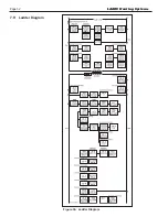
Страница 52: ...Page 52 Figure 36 Ladder Diagram 7 H Ladder Diagram LAARS Heating Systems...
Страница 100: ...Page 100 Parts Illustration 4 Internal Components Sizes 750 850 LAARS Heating Systems...
Страница 102: ...Page 102 Parts Illustration 6 Gas Train Components Sizes 600 850 LAARS Heating Systems...
Страница 103: ...Page 103 Parts Illustration 7 Heat Exchanger Components 68A Sizes 285 NEOTHERM Commercial Boilers and Water Heaters...

