Table of Contents
i
LAARS Heating Systems
SECTION 1
GENERAL INFORMATION
1.A
Introduction .......................................................
5
1.B
Warranty ...........................................................
5
1.C
Model Identification ...........................................
5
1.D
Safety Notes .....................................................
6
1.E
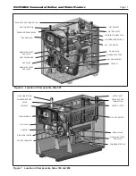
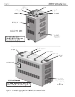
Model Overview ...............................................
8
1.F
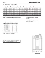
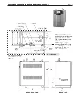
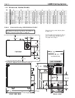
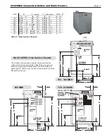
Dimensions, Indoor Models ............................
14
1.G
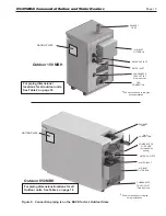
Dimensions, Outdoor Models .........................
16
1.H
The Installation Kit (installation parts box). ....
18
SECTION 2
LOCATING THE UNIT
2.A
General Information ........................................
20
2.B
Locating Appliance for Correct Vent Distance
from Outside Wall or Roof Termination
...........
20
SECTION 3
VENTING AND COMBUSTION AIR
3.A
General Venting ..............................................
21
3.B
Combustion Air ...............................................
21
3.C
Venting ............................................................
24
3.D
Common Venting ............................................
26
3.E
Locating Vent and Combustion Air Terminals .
26
3.F
Common Vent Test .........................................
30
SECTION 4
GAS SUPPLY AND PIPING
.............................
31
SECTION 5
PUMP REQUIREMENTS
5.A
Boiler Flow and Head Requirements - Boiler .
32
5.B
Water Heater Flow and
Head Requirements - Heater ..........................
32
SECTION 6
WATER CONNECTIONS
6.A Boiler ..................................................... 34
6.A.1 Boiler Water Piping ........................................
34
6.A.2 Boiler Cold Water Make-Up ............................
34
6.A.3 Condensate Drain ...........................................
35
6.A.4 Freeze Protection ...........................................
35
6.A.5 Boiler Suggested Piping Schematics ..............
35
6.A.6 Recognized Chemicals ...................................
36
6.B
Water Heater ......................................... 42
6.B.1 Heater Water Quality ......................................
42
6.B.2 Piping Requirements ......................................
42
6.B.3 Cold Water Make-Up ......................................
42
6.B.4 Condensate Drain ...........................................
42
6.B.5 Freeze Protection ...........................................
42
6.B.6 Heater Suggested Piping Schematics ............
42
6.B.7 Heater Suggested Pumps ..............................
43
SECTION 7
INSTALLATION AND WIRING
7.A
Installation Warnings ......................................
45
7.B
Main Power Connections ................................
45
7.B.1 Pump Connections and Operation .................
45
7.B.2 Vari-Prime
(optional variable speed pump control) .....
46
7.C
Hydronic Heating Using
External Modulation Control ..........................
46
7.D
Optional Field Connections ............................
46
7.E
Lead Lag Connections ....................................
48
7.F
Building Automation System Connections ......
49
7.G
System Wiring Diagram ..................................
51
7.H
Ladder Diagram ..............................................
52
Содержание Neotherm NTH
Страница 4: ...LAARS Heating Systems...
Страница 36: ...Page 36 Figure 22 Hydronic Piping Single Boiler Zoning with Circulators LAARS Heating Systems...
Страница 52: ...Page 52 Figure 36 Ladder Diagram 7 H Ladder Diagram LAARS Heating Systems...
Страница 100: ...Page 100 Parts Illustration 4 Internal Components Sizes 750 850 LAARS Heating Systems...
Страница 102: ...Page 102 Parts Illustration 6 Gas Train Components Sizes 600 850 LAARS Heating Systems...
Страница 103: ...Page 103 Parts Illustration 7 Heat Exchanger Components 68A Sizes 285 NEOTHERM Commercial Boilers and Water Heaters...


