background image


p. 50 


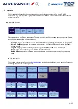
5.2  Position Control 


Selectable from the 

Page Navigation Toolbar

the Position Control tab suite comprises 3 tabs 

providing access to the following pages: 


Reposition

 page which allows you to reposition the aircraft relative to any selected 

airport and runway. 


Aircraft Slew

 page. 


Pushbacks

 page. 


5.2.1 

Reposition 

This page is selectable from the 

Position Control

 tab suite and the 

Crash Conditions

 page 

and allows you to reposition the aircraft relative to any selected airport and runway. 

To initiate a reposition, select the appropriate touchpoint. Flight freeze is set automatically 
during the reposition. When the reposition is completed, deselect Flight Freeze to continue 
the training exercise. 


Содержание B787 Flight Simulator

Страница 1: ...Instructor Manual Air France B787 L3 Simulator ...

Страница 2: ...ator Instructor Manual Chapter 0 Table of contents Table of contents 1 General Page 3 2 Simulator Checklist Page 23 3 IOS Station Page 26 4 Data Entry Page 31 5 IOS PAGES Page 42 6 Malfunction Description document Page 106 ...

Страница 3: ...2 Copyright 4 1 1 3 Contact details 4 1 2 Acronyms and Abbreviations 5 1 2 1 6D 5 1 2 2 A 5 1 2 3 B 6 1 2 4 C 6 1 2 5 D 8 1 2 6 E 9 1 2 7 F 11 1 2 8 H 12 1 2 9 I 13 1 2 10 J 14 1 2 11 K 14 1 2 12 M 14 1 2 13 N 15 1 2 14 O 16 1 2 15 P 16 1 2 16 Q 17 1 2 17 R 17 1 2 18 S 18 1 2 19 T 20 1 2 20 U 21 1 2 21 V 21 1 2 22 W 22 1 2 23 X 22 1 2 24 Z 22 ...

Страница 4: ... the available Malfunctions and Visual Scenes can be obtained by contacting Customer Support or Simulator Engineering The available JAR STD Certified Visual Scenes can be referenced via the Instructor Station through the Airport Selection page 1 1 2Copyright No part of this manual or its extracts may be reproduced in any form by print photocopy microfilm or any other means without written permissi...

Страница 5: ...r fibre optic cables ADF Automatic Direction Finder An aircraft navigation system AFDX Avionics Full Duplex Switched Ethernet An aircraft Ethernet protocol now part of ARINC 664 AGP Accelerated Graphics Port An interface specification that lets 3D graphics display quickly on personal computers AHU Air Handling Unit A free standing generator of air for equipment cooling and flightdeck environmental...

Страница 6: ...drome Terminal Information System A communications system in which a ground station transmits audio messages conveying current airfield weather and operational information to the flight crew 1 2 3 B Item Description Explanation BAM Backlight Adaption Module An interface board to provide lighting supplies to simulated aircraft panels BAM 4 Quad Backlight Adaption Module A Backlight Adaption Module ...

Страница 7: ...data CLDG Control LoaDinG Associated or part of the Control Loading System CLS Control Loading System Simulator system providing feel for aircraft controls CMOS Complementary Metal Oxide Semiconductor A type of semiconductor CMOS semiconductors use both NMOS negative polarity and PMOS positive polarity circuits Since only one of the circuit types is on at any given time CMOS chips require less pow...

Страница 8: ...ng systems DIAMOND DIAgnostic MONitoring and Display The simulator real time diagnostic and health warning system DID Device IDentity Hardware Confidence Test utility DiGIT Distributed Graphical Interface Tool DiGIT is a Graphical User Interface GUI tool that provides a touch screen orientated Human Machine Interface HMI The prime use of DiGIT is the IOS DIMM Dual In line Memory Module A small cir...

Страница 9: ... DU Display Unit Flightdeck Equipment to display information DV Direct Vision Part of the flightdeck window DVD Digital Versatile Disc Rewritable optical disc for data storage DVM Digital Volt Meter Measuring instrument 1 2 6 E Item Description Explanation ECAM Electronic Centralised Aircraft Monitor Avionic unit ECL Electrical Control Loading Control loading system which is loaded by electrical s...

Страница 10: ...Ground Bus Electrical Ground Return path EGPWC Enhanced Ground Proximity Warning Computer Aircraft item part of the EGPWS EGPWS Enhanced Ground Proximity Warning System Aircraft system used to give near terrain warnings EIDE Enhanced Integrated Drive Electronics An interface for connecting devices like the hard disk to a computer ELAC Elevator and Aileron Computer A flight control computer on Airb...

Страница 11: ...ogy for Local Area Networks Xerox Corporation Trade Name 1 2 7 F Item Description Explanation FAM Frequency Adaptation Module A board used in the interface to provide either variable frequency or pulse coded modulating output FANS Future Air Navigation System Aircraft Navigation System FCU Flight Control Unit FFIOS Forward Facing IOS Seat located onboard which provides the facilities required to c...

Страница 12: ...escription Explanation HF High Frequency Frequency band or equipment associated with an aircraft communications system HMI Human Machine Interface An interface that allows a user to control and monitor a system normally with a touchscreen or a keyboard and mouse and a display HMON Software utility HMI Human Machine Interface Part of the Simulator or System that is used to enable a person to intera...

Страница 13: ...IO Input Output A part or the passing of information in or out of a computer system on the simulator it normally relates to the interface between the computer system and the controls indicators and equipment that is part of the simulated flightdeck and environment IOS Instructor Operating Station Position located on board which provides the facilities required to control and monitor both crew and ...

Страница 14: ...n Explanation LAN Local Area Network High speed communications network between computers LCD Liquid Crystal Display A display LED Light Emitting Diode A semi conductor device used as an indicator on boards LHS Left hand Side Log_Book Log Book An electronic logbook to record specific issues to be communicated between team members online part of the simulator Virtual Master Menu VMM LRU Line Replaca...

Страница 15: ... System MIDI Musical Instrument Digital Interface Interface standard for serial data related to sound and music MIC Microphone The audio signal from the microphone MIO Modular Input Output Board used in the interface MIO DSP Modular Input Output DSP Part of the CAMIO board used in the COS and MOS MISC Miscellaneous Used as a label 1 2 13 N Item Description Explanation NDT Navigation Data Tool The ...

Страница 16: ...erface Board used in the modular Input Output system PC Personal Computer A general purpose microcomputer PCI Peripheral Component Interconnect A local bus standard PCU Pre charge Unit Gives the EM2K motion system pressure by charging the accumulators in the system with hydraulic fluid PGG PCI Graphics Generator PE Protective Earth Part of the simulator earthing system PED Pedestal That part of th...

Страница 17: ...sory TCAS Warning RACE Retargeted Avionics Computing Element A proprietary processor board RAID Redundant Arrays of Independent Disks A data storage and backup system RAM Random Access Memory A type of computer memory that can be accessed from time to time that is any byte of memory can be accessed There are two basic types of RAM Dynamic RAM DRAM and Static RAM SRAM RCS Revision Control System Th...

Страница 18: ...s RTP Radio Tuning Panel Communications system control unit RTX Real Time eXecutive RX Receive or Receiver To receive or input voice or data associated with communications systems 1 2 18 S Item Description Explanation SATCOM Satellite Communications Aircraft communications system SBC Single Board Computer A complete computer built on a single circuit board with microprocessor s memory input output...

Страница 19: ...ng A function of aircraft communications systems allows the airline operational staff to selective call one aircraft SIFONIN A software controlled relay used to monitor board status SGU Signal Generator Unit Avionics unit Sim Control Simulator Control Is a container of generic scripts to control the loading starting and stopping of both RACE and native Windows applications It also provides a set o...

Страница 20: ...s a workshop or bench procedure SSP Simulator Support Platform Computer used to support Simulator sounds and software loading of the Host Real Time Platform SW Switch Used as a label 1 2 19 T Item Description Explanation T123 Type 1 2 and 3 rehosted software from Airbus TA Traffic Advisory TCAS Warning TCAS Traffic alert and Collision Avoidance System Aircraft avionics system used to warn and advi...

Страница 21: ...source independent from the building wall isolators USB Universal Serial Bus An external bus standard used to connect peripherals to a computer 1 2 21 V Item Description Explanation VAU Vector Arc Unit ASIC component for drawing lines and arcs VDIM Voltage Dimmable Aircraft lighting supply voltage varies to control flightdeck panel lighting VDK Vertex Development Kit VGA Video Graphics Adaptor A s...

Страница 22: ...ds body for the Internet WAGS Windows Autotest Generation System An integrated collection of tools that can be used for testing and recording the performance of simulation software WXR Weather Radar Aircraft navigation system 1 2 23 X Item Description Explanation XHTML Extensible Hypertext Markup Language W3C Format used for SOLiD XML Extensible Markup Language W3C Format 1 2 24 Z Item Description...

Страница 23: ...structor Manual Chapter 2 Simulator Checklist CHAPTER 2 2 General 24 2 1 Instructor Station Pre flight checklist 24 2 2 Control Loading 24 2 3 Motion System 24 2 4 During Operation 25 2 5 Instructor Station Post flight checklist 25 ...

Страница 24: ... Make sure that all items tools spare parts personal belongings test and access equipment are clear of the control loading system Make sure that all persons on the flight deck know that the control loading system is to be engaged 2 3Motion System Before you operate the motion system Make sure that no persons are in areas of the flight deck where they could be exposed to hazards when the motion sys...

Страница 25: ...h their seat belt fastened until the flight compartment settles to the access position When the motion is disengaged make sure that all persons stay seated with their seat belt fastened until the simulator settles to the access position In normal use the instructor seat should only be moved using the seat FWD and BACK controls on the IOS control panel make sure that the simulator is in the parked ...

Страница 26: ...tor System 27 3 2 Emergency Stop Buttons 29 3 3 Horizontal and Swing Arm Assembly Adjustment Lever 29 3 4 Main Control Assembly 29 3 5 Audio Interface Assembly 29 3 5 1 Audio Control Panel 28 3 5 2 Audio and USB interface assembly 28 3 5 3 Loudspeaker 30 3 5 4 Personal Equipment 30 3 6 Oxygen Mask 30 3 7 IOS Buttons 30 3 7 1 Seat Controls 30 3 7 2 Control Panel 30 ...

Страница 27: ... flight deck the Main Control Assembly contains all the control and displays required by the instructor to control and monitor the actions of both the crew and the simulator are mounted on the instructors seat Instructor Seat and Main Control Assembly 1 Main Control Assembly 2 Emergency Stop Button Forward Control Panel 3 Support Arm Assembly 4 Seat Mounting Plate Assembly 5 Swing Arm Adjustment L...

Страница 28: ...p 28 Bump Switch Emergency Stop Pilot side Oxygen Stowage Box and Mask ...

Страница 29: ...Assembly The Main Control Assembly contains the 19 touch screen display screens control panel local PSUs single phase distribution terminal blocks bump switch control and an Audio Interface Assembly 3 5Audio Interface Assembly The Instructor has the following equipment associated with communications Audio Control Panel Comms Sockets Panel Loudspeakers Personnel Equipment 3 5 1 Audio Control Panel ...

Страница 30: ...trols FWD BACK UP DWN The seat may also be moved manually using the Horizontal Travel Lever This lever disconnects the drive from the horizontal motor and allows the user to manually move the seat backwards and forwards along the seat track e g during Emergency Power Off Do not move the seat when extrem motion is in use uprt buffets 3 7 2 Control Panel The IOS Control Panel includes the following ...

Страница 31: ...uctor Manual Chapter 4 Data Entry Section Title Page 4 1 Flat Panel Displays 32 4 2 Page Display Area 33 4 3 Parameter Readout 34 4 4 Overlays 34 4 4 1 Slew Tool 36 4 4 2 Alphanumeric Keypad 36 4 4 3 Pop Up Menu 37 4 5 Side Toolbar 37 ...

Страница 32: ...p 32 4 1Flat Panel Displays Typical B787 display configuration ...

Страница 33: ...n selected displays another page In this example Preset Weather page would be displayed Buttons Three types of button are used on the pages Direct action When selected associated function is activated or deactivated immediately In this example Standard Day weather conditions would be set up Page selection indicated by the small arrow at the bottom right corner of the button When selected displays ...

Страница 34: ...f a number of flight parameters e g altitude heading details of the currently active airport ICAO code runway in use ILS frequency and also displays a dynamic readout showing messages relating to simulator status e g malfunction active wind shear selected freeze selected This information is displayed on all pages except Plot pages Lesson pages Maintenance pages Area Map display full screen Circuit...

Страница 35: ...last input If you select Cancel the overlay is removed from the display and the parameter reverts to its previous state When entering data you will need to enter the figures exactly as required except when entering heading values when the leading zeros are not required 030 can be entered as 30 Latitude and longitude values can be entered as N S E or W in degrees minutes seconds and tenths of secon...

Страница 36: ...eric Keypad The Alphanumeric Keypad see below is displayed automatically when a touch point is selected which requires an alphanumeric data input Two formats of the keypad are available CDU and PC QWERTY The format displayed is determined by which format was last used A button PC CDU on the keypad will allow you to select the other format The current entry is shown on the overlay The display line ...

Страница 37: ...ide access to the pages The same buttons are displayed on control pages and malfunction pages On map pages some of the buttons are replaced with buttons providing access to functions which are only relevant to map page operation On lesson pages plot pages the CB Panels Index page and the ECL Normal Checklist page the page display extends the full width of the screen and toolbar buttons relevant to...

Страница 38: ...hich allows you to suspend and restart all or some of the simulated systems and to reset the aircraft systems to normal operating conditions Tabs presented are Main Freezes Resets System Resets Help Displays the Instructor Reference Manual page associated with the displayed page Print Prints a copy of the page on the hard copy printer located outside the simulator in the computer room Plots Data D...

Страница 39: ...ve to the radio navigational facilities Also additional buttons are presented on the RH side of the screen such as Mode Range De Clutter Full Screen A C Slews Wind Slew Rng Brg Sel On Map Storm Control Lesson Plan Displays Lesson Plans Control drop down list which lists the available lesson plans to allow you to select the appropriate lesson plan for your training exercise When selecting a lesson ...

Страница 40: ...ccess to TCAS scenarios tabs Arpt Traff Access to Airport Traffic tab additional buttons Scenario control Play Stop Load Sim Ctrl Access to simulator control tabs Devices Tools Snapshot IOS e Print Lesson Plan Aircraft Upsets Smoke Status Shows the following tabs Malf CB Status Crash Conditions Flight Conditions CNIA Controls not in agreement Motion Interlocks Sim message log Repeats allows select...

Страница 41: ...p 41 Status Window Displays the Malfunction CB Status on the LH page which displays the status of malfunctions circuit breakers radio stations and other entities ...

Страница 42: ...irport 55 5 3 1 A C North Up 56 5 3 2 A C Heading Up 57 5 3 3 The following selections are available 57 5 3 4 Map Toolbar 57 5 3 5 Map Declutter 58 5 3 6 A C SLEW 59 5 3 7 Range Bearing 59 5 3 8 Select Entity On Map 60 5 3 9 Storm Control 60 5 3 10 Storm Position 61 5 3 11 Storm Rotation 62 5 4 Navigation Communications 62 5 4 1 Comms 62 5 4 2 ATIS 63 5 4 3 ACARS 65 5 4 4 Radio Stations 65 5 4 5 G...

Страница 43: ...9 2 Non Repeatable Routes 81 5 9 3 Runway Touchdown Intervals 81 5 9 4 Scenario Options 81 5 10 Freeze Resets 82 5 10 1 Freeze Resets 82 5 10 2 System Resets 1 84 5 11 Environment Control 84 5 11 1 Basic 85 5 11 2 Cloud 86 5 11 3 Atmos 87 5 11 4 Visual Runway Conds 88 5 11 5 Airfield Lighting 89 5 11 6 SMGCS 90 5 11 7 Windshear 90 5 11 8 Microburst Predictive Windshear 91 5 11 9 Multi Weather 91 5...

Страница 44: ... 5 13 2 Snapshot 98 5 13 3 IOS e Print 100 5 13 4 Lesson Plan Index 100 5 13 5 Aircraft Upsets 100 5 13 6 Available Upsets 101 5 13 7 Smoke 102 5 14 Traffic 102 5 14 1 Predictable Scenarios 103 5 14 2 Editable Scenarios 104 5 14 3 Random Traffic 105 5 14 4 Airport Traffic 105 ...

Страница 45: ... Services page which allows you to perform functions normally undertaken on the ground Aircraft Weights page which allows you to select the fuel loading and centre of gravity for the aircraft Flight Plan page which allows you to configure the FMC with route information Doors page which allows you to control the aircraft doors Quick Setup page which allows you to quickly set up a training exercise ...

Страница 46: ...ned at the gate but not at generic airports The marshaller is automatically deselected by instructor action when the aircraft has stopped at the gate and the park brake has been applied for 10 seconds during gate reposition when pushback is in progess IRS Instant Align Initiates an instantaneous re alignment of the inertial reference system Hydraulic Reservoir Quantity Left Center Right Allows you...

Страница 47: ... you to set the number of passengers but maximum is limited by Aircraft variant Gross Weight CG Allows you to select the centre of gravity as a percentage of mean aerodynamic chord MAC Left Main Tank Center Tank Right Main Tank Allows you to select the fuel load in each of the fuel tanks on the aircraft Presets Displays a pop up menu which allows you to select from a number of preset values for ze...

Страница 48: ...roll up down through the list of available flight plans Load to FMC Programs the FMC with the information from the selected stored route Save from FMC Saves the existing FMC load configuration to the selected route number for future use Delete Delete selected flight plan Edit Cmmnt Allows you to edit the comment for the selected flight plan 5 1 4 Doors This page is selectable from the Aircraft Con...

Страница 49: ... the non normal checklist to idle Norm Complete Access the normal checklist page 5 1 5 Quick Setup This page is selectable from the Aircraft Control tab suite and allows you to quickly set up a training exercise from a single page To set up a training exercise Select Predefined Setup A pop up menu is displayed listing the available setups Select the required setup The predefined values are display...

Страница 50: ...port and runway Aircraft Slew page Pushbacks page 5 2 1 Reposition This page is selectable from the Position Control tab suite and the Crash Conditions page and allows you to reposition the aircraft relative to any selected airport and runway To initiate a reposition select the appropriate touchpoint Flight freeze is set automatically during the reposition When the reposition is completed deselect...

Страница 51: ...ch allows you to select the ramp and gate to be used for the reposition Special Repositions Special Repositions allow unique in air repositions to be set up for a particular airport and runway This is in addition to the normal in air repositions available from the Reposition page The Special Reposition button on the IOS is only authorised when Special Repositions have been set up for the repositio...

Страница 52: ...2 nm Left 10 nm 2 nm Left 3000 ft Calculated Up 1 stowed 10 nm 2 nm Right 10 nm 2 nm Right RW On G S Calculated Up 1 stowed Final 10 nm 10 nm ON LOC RW On G S Calculated Up 1 stowed Final 8 nm 8 nm ON LOC RW On G S Calculated Up 1 stowed Final 6 nm 6 nm ON LOC RW On G S Calculated Up 2 stowed Final 4 nm 4 nm ON LOC RW On G S Calculated Down Full armed Final 2 nm 2 nm ON LOC RW On G S Calculated Do...

Страница 53: ...ion Geographic Allows aircraft to be repositioned relative to its geographic heading Selecting a touchpoint moves the aircraft in that direction Releasing the touchpoint stops the action Heading Altitude AMSL Speed Mach No Allow value of associated parameters to be changed Speed Up Allows aircraft ground speed to be changed other aircraft parameters are not affected Target Lat Lon Allow geographic...

Страница 54: ...ed to the aircraft Thrust to high such that the tug would be pushed back Aircraft moving Aircraft in Flight Note to activate selected any pushback prior the Steering Locked Out needs to be activated Steering Locked Out Disconnects nose wheel steering from rudder pedals Nose Right Aircraft is reversed from ramp and turned 90 to the left Nose Left Aircraft is reversed from ramp and turned 90 to the ...

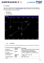
Страница 55: ...p 5 3 1 Ref Airport The map is centred on the currently active airport with true north at the top of the screen The following elements can be displayed Colour Comments NDB Radio Navigation Stations Green Normal Displayed with appropriate symbols identification code and frequency VHF Radio Navigation Stations and waypoints Cyan Magenta Red Normal Displayed with appropriate symbols identification co...

Страница 56: ...ILS and LDA fans Yellow Orientated to the true heading of the localiser beam Identification code and frequency of ILS and LDA Yellow Runways Grey Orientated to the true heading of the runway axis Identification code of runway in use Grey The map range can be set to one of a number of preset values to maintain the present map centre and the current aircraft position on the map The aircraft track is...

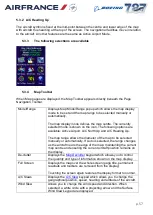
Страница 57: ...e Airport A C North Up and A C Heading Up The map range allows the diameter of the map to be selected manually or automatically If Auto is selected the range changes as the aircraft nears the edge of the map maintaining the current map centre and ensuring the current aircraft position remains on the display De clutter Displays the Map Declutter keypad which allows you to control the quantity and t...

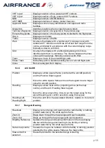
Страница 58: ...ail restore the facility Display range bearing information Set the facility as the map centre Selecting range bearing displays the ident bearing and range of the facility in the map display title bar Storm Ctrl Displays the Storm Control menu to allow you to control and modify the storm models 5 3 5 Map Declutter This popup is displayed when De clutter is selected on the Map Toolbar Auto Selects d...

Страница 59: ...trace of aircraft flight path Close Removes keypad from display 5 3 6 A C SLEW Position Displays a white square frame centred at the aircraft position and the Position Slew keypad Move the white square frame and use the keypad to set a target value for aircraft position Heading Displays a white circle with a projecting arrow at the map centre and the A C Heading Slew keypad Move the arrow around t...

Страница 60: ...pe Zoom In Steps down through the map ranges with each selection Zoom Out Steps up through the map ranges with each selection OK Displays the Select Station menu of details for those stations within the area of interest defined by the white circle The menu displays Nothing Found if there are no stations within the area of interest Enter Ident Displays the alphanumeric keypad to allow a facility to...

Страница 61: ...t speed and direction Move the arrowhead around the circle to select the direction and away from the circle to select the speed Confirm the selection by selecting OK on the keypad BRIGHTNESS Displays the Storm Brightness keypad to allow you to control the intensity of the storm image on the Map display Select High Medium or Low NOTE The outline storm display is always shown at High brightness MAP ...

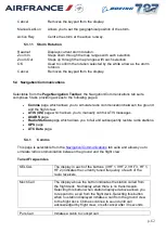
Страница 62: ... allows you to manually control ATIS messages ACARS page Radio Stations page which allows you to fail and subsequently restore radio stations GPS page ATC Data page 5 4 1 Comms This page is selectable from the Navigation Communications tab suite and allows you to simulate radio communication between the ground and the flight crew Tuned Frequencies SELCAL The display in each of the buttons VHF 1 VH...

Страница 63: ...ity Emergency Safety Non Safety Public of the satcom voice call Service Interphone Switches flight interphone comms from the instructors station to service interphone mode The crew can only communicate with the instructor using flight interphone if the overhead panel service interphone switch is selected on Normal crew flight interphone operation is unaffected Comm Noise Allows you to set a level ...

Страница 64: ... changed for currently selected airport ILS Status Allows you to select the type of failure associated with the ILS on the currently active runway UTC Runway Condition Precip Visibility Restriction Cloud 1 Condition Cloud 2 Condition Allow the condition of the associated parameter to be changed Wind Direction Wind Speed Visibility Cloud 1 Height Cloud 2 Height Field Temperature Dew Point QNH ICAO ...

Страница 65: ...VHF NavAid Display the alphanumeric keypad to allow you to enter a radio station identifier After the identifier has been entered a pop up menu is displayed to allow you to select a specific radio aid at the station NOTE If the keypad identifier is unknown the message Nothing Found is displayed on the pop up menu NDB NavAid Airway Marker ILS Select by Airport Runway Reference Airport ICAO Code Dis...

Страница 66: ...alue ATC logon disconnection is independent of changes in aircraft position Inhibit ATC Logon Logon requests initiated either by the crew or automatically in response to a change in local centre are refused Existing ATC connection are terminated on receipt of a logon request Ground Stn Status Displays a popup menu to allow you to change the status of the ground station ATC Data Reset Resets the AT...

Страница 67: ...hange Allow you to set the event parameters that will initiate the report Request Event Report Sends signal to the aircraft requesting report to be sent when the specified event is reached Cancel Event Report Sends signal to the aircraft cancelling the event report Create CPDLC Messages This page is selectable from the ATC Data page and allows you to set up a CPDLC message for transmission to the ...

Страница 68: ...essage to the aircraft Use the SCROLL UP SCROLL DOWN buttons to scroll through the routes messages Send Uplink Transmits the message in the Uplink window to the aircraft ATC Data Reset Resets the ATC DATA simulation to status at start of training exercise Message log is cleared All existing ADS and CPDLC links are disconnected Any messages queued for transmission are deleted CPDLC Log This overlay...

Страница 69: ...altitude is reached or manually by selecting a button In addition it is possible to have non sequential events in the lesson plan which do not form part of the sequential flow but can be selected at any time The lesson plans are created off line using the Lesson Plan Editor utility The lesson plans can be displayed in either Profile view or List view NOTE A lesson plan may be locked in either view...

Страница 70: ... red when the event is executing The button changes to dark green when the event is completed If the lesson plan is not running all the buttons are grey and cannot be selected Events may have more than one set of associated actions and you can change the set that is active for the current lesson plan To select a different set of actions touch the button and then select the appropriate button on th...

Страница 71: ...E A lesson plan can be locked in either mode from the Lesson Plan Editor View which switches between Profile and List view Back and Forward arrow buttons which allow you to scroll through the lesson plan The lesson stops automatically when the last event has finished executing 5 6 Maintenance Index This page is selectable from the Page Navigation Toolbar and lists all the available Maintenance pag...

Страница 72: ...an be set to take immediate effect or can be armed to take effect when specified aircraft parameters reach a pre determined value The Malfunction Mode touchpoint allows you to select either Direct or Arm In Direct mode selecting a malfunction touchpoint immediately activates or de activates the associated malfunction In Arm mode selecting a malfunction displays a pop up menu with selections accord...

Страница 73: ...he Flap Lever pop up menu which allows you to select one of a number of flap lever positions as the trigger condition Ldg Gear Lever Displays the Ldg Gear Lever pop up menu which allows you to select either UP or DOWN as the trigger condition Heading Displays transition options see below Selecting an option displays the numeric keypad to allow you to enter a heading value as the trigger condition ...

Страница 74: ...ter or lesser value rises above Sets the condition to activate when the parameter changes to any value above the specified value from a lesser value less than Sets the condition to activate whenever the value is less than the specified value greater than Sets the condition to activate whenever the value is greater than the specified value 5 8 Plots Selectable from the Page Navigation Toolbar the P...

Страница 75: ...eslope beams are displayed with deviation lines at 1 and 2 dots either side of the beam centreline By default the localiser and glideslope lines flash when the aircraft is within the proximity box 4Nm of the active runway but outside of the glideslope beam The plots are erased under the following conditions Change in active runway When the Erase Track button is selected by the instructor The later...

Страница 76: ...he aircraft s position TCH This is the height at which the aircraft crosses the runway threshold as it flies down the ILS glideslope T D Dist This is the point to point distance from the aircraft to the active runway touchdown zone This touchdown zone is represented on most runways as 2 large white blocks either side of the runway centreline approximately 1000ft from the runway threshold T D ROD E...

Страница 77: ...ny malfunction is activated while this plot is active The following data readouts and buttons are displayed in the plot toolbar area directly below the Page Navigation Toolbar Elevation Rwy Cond Gusting To Erase Track Erases the current plot 5 8 3 Departure This page is selectable from the Plots tab suite and consists of three graphs Lateral deviation distance left right from the extended runway c...

Страница 78: ...tons are displayed in the plot toolbar area directly below the Page Navigation Toolbar Elevation Rwy Cond Gusting To Erase Track Erases the current plot Scale Allows you to change the scale of the plot auto high medium low 5 8 4 T O and Landing Performance This page is selectable from the Plots tab suite and displays the values of various aircraft parameters during take off landing or go around ph...

Страница 79: ...d After calibrated airspeed has exceeded 40 kt Eng Fail Type 1 If N1 on either engine 70 and both TLAs have not changed by more than 1 Power Idle Type 1 If on ground and both TLAs 5 Brake On Type 1 If on ground and either of the outboard tyre forces 1000 lbs Reversers Type 1 If on ground and either TLA 90 VStop 15 Ft Ht AGL Type 1 If radio altitude 15 ft 35 Ff Ht AGL Type 1 If radio altitude 35 ft...

Страница 80: ...g Phase and Either TLA 50 and Rate of climb is positive and Radio altitude 2000 ft App Climb Grad Type 2 Updated in real time with the average gradient to the current point from where a GA Phase has been detected and the gear is up This is continually updated to the point where the GA Phase is no longer valid This last calculated gradient is effectively the average over the whole of the segment Th...

Страница 81: ...essed or when triggered by an ownship event see Play Trigger Structure Select a row to load clear or stop a non repeatable route 5 9 3 Runway Touchdown Intervals Configure Intervals Displays a popup menu to allow you to set touchdown intervals Selected intervals times are displayed for each runway 5 9 4 Scenario Options Ownship Priority Ownship Priority is used when the ownship is taking off and c...

Страница 82: ...rating conditions System Resets 1 page which allows you to reset aircraft systems and temperatures to normal operating conditions System Resets 2 page which allows you to reset the associated comptuers to normal operating conditions 5 10 1 Freeze Resets This page is selectable from the Freeze Resets tab suite and allows you to suspend and restart all or some of the simulated systems and to reset t...

Страница 83: ...s all failed navigational facilities and clears all circuit breaker trip conditions NOTE Popped circuit breakers must be manually reset Environment Reset No storms standard atmosphere no icing conditions no weather effects no microburst wind shear no wind and no wind gradient CAVOK Horizon bright Runway dry and smooth visual day conditions no turbulence no TCAS no ground traffic Airport lighting r...

Страница 84: ...ed systems ATA 35 Oxygen Resets all ATA related systems ATA 49 APU Resets all ATA related systems ATA 52 Doors Resets all ATA related systems ATA 71 Engines Resets all ATA related systems Sound Resets the sound system Malfunction Auto Reset 5 11 Environment Control Selectable from the Page Navigation Toolbar the Environment Control tab suite comprises 8 tabs providing access to the following pages...

Страница 85: ...be active for this function to be selectable Field Temperature Allows you to set the temperature at the airport QNH Allows you to set the QNH value QFE Allows you to set the QFE value Visibility Allows you to set the visibility range for the visual scene Fog Allows type of fog to be selected from pop up menu Selecting FOG automatically sets an RVR value Likewise setting an RVR value automatically ...

Страница 86: ...C Delta ISA 0 C Weather Scenario Reset Restarts an active multi weather scenario using the default values loaded upon initial activation of the scenario 5 11 2 Cloud This page is selectable from the Environment Control tab suite and allows you to set various cloud conditions High Altitude Cloud Type Allows you to select Blue Sky or one of a variety of different types of cloud Upper Cloud Layer Top...

Страница 87: ...ou to select icing conditions Surface Layer Wind Dir Spd Allows you to set the wind direction speed Gusting To Allows introduction of pseudo random gusts A surface wind of at least 10 knots must be active for this function to be selectable Turbulence Allows you to select cobblestone or rough air turbulence conditions NOTE Conditions are mutually exclusive Icing Allows you to select icing condition...

Страница 88: ...ct from a number of pre defined setups detailed below Scenario CAVOK CAVU CAT I CAT II CAT IIIA CAT IIIB Non precision Circling Min T O Upper Cloud Top ASL ft Upper Cloud Base ASL ft Upper Cloud Scud Y N No No No No No No No No No Lower Cloud Top ASL ft None None 10000 10000 10000 10000 8000 8000 10000 Lower Cloud Base AGL ft None None 230 130 70 40 1100 1000 400 Lower Cloud Scud Y N No No No No N...

Страница 89: ... set to default whenever a new active runway is selected In Manual mode manually set levels are retained regardless of the runway in use All Lights Intensity Displays popup menu to allow you to set the intensity of all the runway lights to the same level 0 off 5 max Randomize Sets the lighting intensities to random levels Env Lights Display popup menu to allow you to set the intensity of the light...

Страница 90: ...e aircraft to a runway the taxiway lighting from the final HOLD to the runway will only be illuminated when this button is selected Scroll Up Scroll Down These will only be authorised if the page cannot display all of the available SMGCS routes 5 11 7 Windshear This page is selectable from the Environment Control tab suite and allows you to select from a number of pre defined windshear profiles In...

Страница 91: ... given below Position Intensity Distance Distance from Centreline Takeoff 50 1 0 NM On CL Takeoff 50 1 8 NM On CL Approach 50 3 0 NM On CL Approach 50 1 2 NM On CL Approach 50 1 2 NM 0 5 NM Left Approach 50 1 2 NM 0 5 NM Right Approach 50 0 8 NM On CL 5 11 9 Multi Weather This page is selectable from the Environment Control tab suite to allow you to set up a variety of environmental parameters at ...

Страница 92: ...r profile Microburst Displays the currently selected microburst profile Activate Scenario With Current Settings Activates the currently selected settings Weather Scenario Reset Resets weather scenario to normal operating conditions 5 12 Status Monitor Selectable from the Page Navigation Toolbar the Status Monitor tab suite comprises 6 tabs providing access to the following pages Malf CB Status pag...

Страница 93: ...o be set inactive Armed Malfunctions These are identified in yellow text each with its selected arming conditions Selection of an associated button displays a keypad which allows the malfunction definition to be displayed for the arming conditions to be changed for the malfunction to be activated or for it to be disarmed Failed Stations Failed radio stations are identified in cyan text Selection o...

Страница 94: ...conditions coloured amber when their display is enabled blue when it is suppressed NOTE Popped circuit breakers must be manually reset 5 12 2 Crash Conditions This page is selectable from the Status Monitor tab suite If the aircraft crashes Total Freeze is set and this page is displayed with the reason for the crash highlighted Recoverable Crashes Excessive IAS IAS VMO 60 knots VD Excessive MACH M...

Страница 95: ...en if an in air crash is detected select Crash Inhibit This disables the crash monitoring system so that the simulation does not stop if one of the in air crash conditions is detected Select Reset Advisory to cancel advisory warnings 5 12 3 Flight Conditions This page is selectable from the Status Monitor tab suite and displays current value of listed aircraft and environment parameters 5 12 4 Con...

Страница 96: ...play Unit MODU at the motion cabinet in the simulator hall for messages Reset Latches Resets latched conditions to current 5 12 6 Sim Message Log This page is selectable from the Status Monitor tab suite and is used to display critical software error messages that have been logged by software systems that impact training in some way For example errors detected during the loading of some or all of ...

Страница 97: ...e First Officer s HUD display 7 12 1Schematics This page is selectable from the Status Monitor tab suite and displays active schematics for the associated ATA chapter 5 13 Simulator Control Selectable from the Page Navigation Toolbar the Simulator Control tab suite comprises 5 tabs providing access to the following pages Devices Tools page Snapshot page IOS e Print page Lesson Plan page Aircraft U...

Страница 98: ... screen to return to previous page Document Viewer Displays the Document Viewer page Stopwatch Play Select to start stopwatch Stop Select to stop and reset stopwatch 5 13 2 Snapshot This page is selectable from the Simulator Control tab suite The snapshot system allows you to record the condition of the simulator during a flight so that you can re configure the simulator to that condition at a lat...

Страница 99: ...the snapshot slected contains data the snapped values are displayed on the page If you no longer require this snapshot select Erase to clear the data If you do want to retain the snapshot select another number Select Take The simulator conditions are stored in the snapshot and displayed on the page NOTE Armed malfunctions are not recorded as part of the snapshot as they are not active and do not f...

Страница 100: ...fresh the table of file types and names View Allows you to view a file Print Hard Copy Allows you to print the selected files Print Options Opens the Image Operations pop up which allows you to Push Selected Image To Network Push All Images To Network Push Selected Image to USB Push All Images to USB Delete Selected Image Delete All Images Cancel 5 13 4 Lesson Plan Index Refer to chapter 7 5 5 13 ...

Страница 101: ...p 101 5 13 6 Available Upsets UAT 1 Pitch 27 Nose Up Bank 30 Left UAT 2 Pitch 27 Nose Up Bank 30 Right UAT 3 Pitch 15 Nose Dn Bank 30 Left UAT 4 Pitch 15 Nose Dn Bank 30 Right ...

Страница 102: ...e Smoke Request Arms the smoke generator Smoke Volume Ctrl Allows you to select the volume of smoke 25 50 75 100 Generator Status Displays the smoke generators status 5 14 Traffic Selectable from the Page Navigation Toolbar the Traffic tab suite comprises 4 tabs providing access to the following pages Predictable Scenarios page which allows you to setup TCAS scenarios Editable Scenarios page which...

Страница 103: ... If you select an intruder aircraft with no transponder fitted the system will display an ATR42 only This page allows selection of scenarios that will generate a predictable TCAS voice call out The requested voice call out will be generated as long as the own aircraft s manoeuvres are within the limits specified for the selected scenario The Vertical Separation Distance diagram displays the initia...

Страница 104: ...r from this aircraft Initial Relative Altitude Initial altitude of the intruder relative to this aircraft ve is above Transponder Type Intruders fitted TCAS equipment operating mode Selectable are MODE A MODE C MODE S or None Final Bearing Final bearing of intruder from this aircraft or 180 degree ve is right Final Distance Final distance in nautical miles of intruder from this aircraft Final Rela...

Страница 105: ...prediction functions adjust for this aircrafts altitude To consistently demonstrate conflicts this aircraft is best at 15000 feet 5 14 4Airport Traffic This page is selectable from the Traffic tab suite and allows you to control the appearance and movement of up to 6 repeating and 2 non repeating routes These incidents are normally designed to present the aircrew with a hazard in the vicinity of t...

Страница 106: ... will be resumed Runway For Gen Routes For airports with more than one runway auto generics or specifics the Runway for Gen Routes button allows all generic routes routes recorded at a generic airport which can be used anywhere within a scenario to use an alternative reference runway to the active runway The button will only be active before the scenario begins as the routes cannot be altered once...

Страница 107: ...nctions can be found as a separate document tailed to match the latest BP load of the A350 simulator Therefore the list of malfunctions also known as MDD Malfunction Description Document will be separate from this instructor manual In general all malfunctions provided by Boeing will be available in this simulator approximately 270 ...

Отзывы: