KYOKUTOH TM01-KP-00A Скачать руководство пользователя страница 2

ATTENTION TO SAFETY 


Please be sure to read ATTENTION TO SAFETY before using the tip monitor. 


After reading the manual, please keep it to the place where it can be checked easily. 


Please DO NOT disassemble or reconfigure this machine or its parts. 


If the stickers on the back of the monitor has been removed, no warranty or repair service may be recieved. 


When working in the assembly line, please make sure the welding gun is OFF, and the safety from other machines. 


Please turn OFF the power, when replacing the parts or maintenancing. 


When the monitor is not set in a proper way, the monitor may not collect enough information to maintain good 
condition in the welding process. 


When using the monitor, please be sure to turn OFF the welding current. 


This product is not to be used in any 

manner other than that which is specified 

within. We will not be held responsible for 

damage or injury caused as a result of this 

product. 

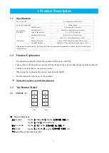
The purpose of the tip monitor is to judge whether the cap tip passes the criteria set in advance to enable automatic 
manufacturing environment. 
The tip monitor must be used with the tip dresser of KYOKUTOH. 
Please DO NOT use the tip monitor other than that which is specified within. We will not be responsible for any 

trouble, repair, accidents caused when used in a way other than that which is specified within. 


Содержание TM01-KP-00A

Страница 1: ...Tip Monitor TMN 01 Instruction Manual Please read this instruction manual carefully before using the device First Edition 2013 04 23 Revised Edition 2021 01 08 V3 02...

Страница 2: ...oper way the monitor may not collect enough information to maintain good condition in the welding process When using the monitor please be sure to turn OFF the welding current This product is not to b...

Страница 3: ...l Interface Setting 3 4 Timing Chart Software Setting 4 1 System Software Structure 4 2 Installation of the Software 4 3 Setting the IP Address of Tip Monitor 4 4 Setting the System Setting Tool 4 5 S...

Страница 4: ...he environmental resistance above and set the device away from water dust etc 1 2 Function Explanation Tip monitor automatically judges the condition of the cap tip OK NG Take a photo of the upper low...

Страница 5: ...TM01 KP 00A Standard 13 6 5R TM01 KP 00B For 120 TM01 KP 00C Plate correspondence to the tip TIP DIA TOP DIA SHAPE CORRESPONDANCE 13 5 8 8R 16 19 9 5R 13 5 8 6 5R 13 5 8 CF120 16 19 13 R20 16 13 16 I...

Страница 6: ...15 cameras can be connected to each computer There must be a power supply from the PoE HUB to the tip monitor Power Supplied from PoE HUB CC Link Connection Set PLC as the master It is required for t...

Страница 7: ...mpatible with Type A Type B Recommend EHB UG2B08 PL2 ELECOM Recommend LAN SW08ES4 MA Logitec Prepare the amount of PoE to supply power for the entire tip monitor Using a slow speed of PoE hub may not...

Страница 8: ...are the amount of PoE to supply power for the entire tip monitor Using a slow speed of PoE hub may not be able to communicaste properly Recommended speed 1 000Mbps Please choose the PoE hub with the r...

Страница 9: ...ng gun pressure we recommend the usage of EQUALIZINGS Please DO NOT place the monitor in which it can be interfered by cables hoses welding robots etc Please make sure the welding gun DOES NOT interfe...

Страница 10: ...picture above and fix it using 2 M6 2 5h7 Pin To protect the sensor from a shock the usage of an equlizer is recommended When purchased with the bracket Attach the monitor to the dresser like the pic...

Страница 11: ...uired Please be sure to check the following items listed below The number of cameras Name of the robot Shape of the cap tip Diameter of the cap tip Way to connect with the PLC Setting Parameters Seria...

Страница 12: ...Shown on the software screen Label 2 No Number used to connect with the PLC Robot Name Name used in the software 1 Number of letters must be more than 4 less than 8 2 Special Characters may not be use...

Страница 13: ...ons Network Connections Local Area Connection Internet Protocol ICP IP Properties With Windows7 Control Panel View by Small icons Network and Sharing Center Change adapter setting Right Click Local Ar...

Страница 14: ...ght Click The lower left of a screen Device Manager Network adaptors Click Click the name Unselect Allow the computer to turn off this device to save power DO NOT set the PC to activate background sof...

Страница 15: ...the attached software and the PLC Confirm the setting which will be used for the PLC CC Link Set Up Mitsubishi Electric Q80BD J61BT11N Set the allotment of Station No Type Set the Occupied Sta as Occ...

Страница 16: ...13...

Страница 17: ...RM21 By using devNetSetting_slave exe set up the DeviceNet slaves To connect the PCI and I F board the setting of is required The Byte rate of I O depends on the amount of using monitors The software...

Страница 18: ...15...

Страница 19: ...OFF and turns OFF the result Release the pressure When OK judge was made When NG judge was made Dia Judge NG Signal Dia Judge is OFF REM Judge NG Signal REM Judge is OFF The camera signal will turn O...

Страница 20: ...WA SVGUNCL GUN 1 PRESSCL 4 ON Start pressurizing WAIT IN ON Wait for the signal input SVGUNCL GUN 1 PRESSCL 4 OFF Stop pressurizing The data strobe signal that written as XOE1 in the below ladder diag...

Страница 21: ...d below IPAddress Setting Tool A set up tool for the IP address of the tip monitor System Setting Tool A set up tool for the system of the tip monitor Camera Parameter Setting Tool A set up tool for e...

Страница 22: ...finished Insert the attached CD into the PC Activate the SETUP exe Right Click SETUP exe Run as administrator Select language and click OK Read the SOFTWARE LICENCE AGREEMENT carefully and when agreed...

Страница 23: ...ion the setting will be invalid Please reconnect No duplicate IP address is usable When connecting more than one monitor to a specific PC different IP address must be set to each tip monitor Activate...

Страница 24: ...21 When the dialog below pops up unplug the LAN cable from the tip monitor Reconnect the LAN cable and confirm the setting Do the same to the other tip monitors and the IP setting is finished...

Страница 25: ...System Setting Tool Activate the System Setting Tool The icon will be in the TMN launcher Type in the master password 0000000 then click OK Select the amount of cameras then click OK The system settin...

Страница 26: ...tion 1 2 is optional It can be left blank Indication 1 2 will be shown as the picture below a Cell Layout To show the picture segmentation of the cell is needed When first set the cell allocation will...

Страница 27: ...e is used to identify each robot on the system Therefore it is recommended not to change the robot name after it has been set Set up the connection with the PLC Choose the interface to use to connect...

Страница 28: ...lease shut down other software Judge Record Software etc Then start up System Setting Tool There will be no problem if System Setting Tool is already running Click Language as a picture below Select l...

Страница 29: ...word 0000000 then click OK 1 Before setting up the cap tip needs to be dressed and kept pressured Recommended Pressure 1500N Maximum 3000N THE SETTING MUST BE DONE AFTER THE CAP TIP IS DRESSED IF NOT...

Страница 30: ...elow Click OK If the photograph does not show nor has any errors please recheck the network Also please check if any contaminations or shadows are not on the cap tip as well Click Setting Condition If...

Страница 31: ...28 Choose the character Character upper will be shown like it is in the picture Choose the type of cap tip the diameter of the cap tip Click Go down Character upper...

Страница 32: ...en either of the tips passes the limit Default Both within limit OK judge when both tips passes the limit Area of BlackREM Outer dotted line Judgment objected to totalarea of the tip top Black REM Dia...

Страница 33: ...message will pop up Click and go on Now on please be careful of these listed below Cap tip that has been dressed and pressurizing the monitor Any dust or contaminations are not in the photo No shadows...

Страница 34: ...cross by using the ways a and b a Set the cursor on the center of the cap tip and double click Cursor will show up when setting the mouse on the photograph b Move by using the arrows set on the botto...

Страница 35: ...lly When the message pops up click OK If the auto adjustment fails an error message will appear Please check whether the cap tip is dressed properly and set again Click Adjustment of blue edge Drag th...

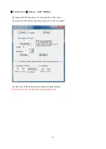
Страница 36: ...33 When finished click OK Click Save Before Adjusting After Adjusting...

Страница 37: ...op up Please confirm the message if same setting shape value is preferred Release the gun Conduct process to all of the tip monitors After finishing all of the settings click Exit CAUTION Expert is on...

Страница 38: ...ftware is activated the camera will take a test shot to make sure the camera is connected properly The test shot is set to take brighter photos than the usual photos When the setting is wrong or the c...

Страница 39: ...ameter Things concerned The threshold value set too severe not enough pressure not adjusted properly to the center blue light not adjusted properly Please recheck the teaching pressure and follow the...

Страница 40: ...causes the system not to work properly Shown with red letters under 15GB Under 3GB the system stops operating Shows the most recently taken photo Click to take a test shot With the test shot no judgm...

Страница 41: ...ws the length of the upper right and lower left blue edges Remainder Shows the of which was recognized black in the cap tip Remain ctr Shows the of which was recognized black in the center of the cap...

Страница 42: ...part should be ordered this way From the bottom Tip Monitor Protection Lens O Ring Pressure Plate When disassembling the monitor please make sure any contaminations or water drops DO NOT enter inside...

Страница 43: ...the lens Please DO NOT rub the lens hard It is recommended to use soft cloth or cotton swab when removing Please DO NOT use Oil Removal Spray on the lens CAUTIONS Please DO NOT disassemble any parts...

Страница 44: ...41 6 List of Consumption Parts Protection Lens 2 pcs TYPE TM01 SU 00A Replacement Qty1set Pressure Plate TYPE TM01 KP Replacement QTY 2pcs O Ring TYPE TM01 LE 201 Replacement Qty 2pcs...

Страница 45: ...ssed NG Damaged Lens Some parts in the window are shown white Spatter on the lens Dust on the lens Chip on the lens The tip is tilted Water drops on the lens The timing of releasing the welding gun is...

Страница 46: ...ough The monitor can only detect tips which has been dressed Please dress the tip before using The monitor can not measure the diameter of the flat tips Use the Camera Setting Tool please reset the ti...

Страница 47: ...3 4 There is a connection error shown when the software is activated The PoE HUB is turned OFF The tip monitor is connected to the port of the PoE HUB without power supply The LAN cable is not connect...

Страница 48: ...n the stickers on the back of the monitor has been removed Any failure resulting from factors other than a defect of our product such as the purchaser s equipment or the design of the purchaser s soft...

Страница 49: ...46 MEMO...

Страница 50: ...com KYOKUTOH CHINA 73 Huagang Street Xiuquan Town Huadu District GuangZhou City GuangDong Province China TEL 86 20 86980880 FAX 86 20 86980890 http www kyokutoh com cn KYOKUTOH THAILAND 339 2 Soi Phat...

Страница 51: ...48...

Отзывы: